|
1
|
VERIFY FREEZE FRAME DATA/SNAPSHOT DATA HAS BEEN RECORDED
• Has the FREEZE FRAME DATA/snapshot data been recorded?
|
Yes
|
Go to the next step.
|
|
No
|
Record the FREEZE FRAME DATA/snapshot data on the repair order, then go to the next step.
|
|
2
|
VERIFY RELATED SERVICE INFORMATION AVAILABILITY
• Verify related Service Information availability.
• Is any related Service Information available?
|
Yes
|
Perform repair or diagnosis according to the available Service Information.
• If the vehicle is not repaired, go to the next step.
|
|
No
|
Go to the next step.
|
|
3
|
VERIFY RELATED PENDING CODE AND/OR DTC
• Switch the ignition off, then ON (engine off).
• Perform the Pending Trouble Code Access Procedure and DTC Reading Procedure.
• Are any other PENDING CODEs and/or DTCs present?
|
Yes
|
Go to the applicable PENDING CODE or DTC inspection.
|
|
No
|
Go to the next step.
|
|
4
|
INSPECT APP SENSOR CONNECTOR CONDITION
• Switch the ignition off.
• Disconnect the APP sensor connector.
• Inspect for poor connection (such as damaged/pulled-out pins, corrosion).
• Is there any malfunction?
|
Yes
|
Repair or replace the connector and/or terminals, then go to Step 15.
|
|
No
|
Go to the next step.
|
|
5
|
INSPECT CMP SENSOR CONNECTOR CONDITION
• Disconnect the CMP sensor connector.
• Inspect for poor connection (such as damaged/pulled-out pins, corrosion).
• Is there any malfunction?
|
Yes
|
Repair or replace the connector and/or terminals, then go to Step 15.
|
|
No
|
Go to the next step.
|
|
6
|
INSPECT EGR COOLER BYPASS VALVE CONNECTOR CONDITION
• Disconnect the EGR cooler bypass valve connector.
• Inspect for poor connection (such as damaged/pulled-out pins, corrosion).
• Is there any malfunction?
|
Yes
|
Repair or replace the connector and/or terminals, then go to Step 15.
|
|
No
|
Go to the next step.
|
|
7
|
INSPECT EGR VALVE CONNECTOR CONDITION
• Disconnect the EGR valve connector.
• Inspect for poor connection (such as damaged/pulled-out pins, corrosion).
• Is there any malfunction?
|
Yes
|
Repair or replace the connector and/or terminals, then go to Step 15.
|
|
No
|
Go to the next step.
|
|
8
|
INSPECT INTAKE SHUTTER VALVE CONNECTOR CONDITION
• Disconnect the intake shutter valve connector.
• Inspect for poor connection (such as damaged/pulled-out pins, corrosion).
• Is there any malfunction?
|
Yes
|
Repair or replace the connector and/or terminals, then go to Step 15.
|
|
No
|
Go to the next step.
|
|
9
|
INSPECT EXHAUST GAS PRESSURE SENSOR NO.1 CONNECTOR CONDITION
• Disconnect the exhaust gas pressure sensor No.1 connector.
• Inspect for poor connection (such as damaged/pulled-out pins, corrosion).
• Is there any malfunction?
|
Yes
|
Repair or replace the connector and/or terminals, then go to Step 15.
|
|
No
|
Go to the next step.
|
|
10
|
INSPECT EXHAUST GAS PRESSURE SENSOR NO.2 CONNECTOR CONDITION
• Disconnect the exhaust gas pressure sensor No.2 connector.
• Inspect for poor connection (such as damaged/pulled-out pins, corrosion).
• Is there any malfunction?
|
Yes
|
Repair or replace the connector and/or terminals, then go to Step 15.
|
|
No
|
Go to the next step.
|
|
11
|
INSPECT MAP SENSOR NO.1 CONNECTOR CONDITION
• Disconnect the MAP sensor No.1 connector.
• Inspect for poor connection (such as damaged/pulled-out pins, corrosion).
• Is there any malfunction?
|
Yes
|
Repair or replace the connector and/or terminals, then go to Step 15.
|
|
No
|
Go to the next step.
|
|
12
|
INSPECT FUEL PRESSURE SENSOR CONNECTOR CONDITION
• Disconnect the fuel pressure sensor connector.
• Inspect for poor connection (such as damaged/pulled-out pins, corrosion).
• Is there any malfunction?
|
Yes
|
Repair or replace the connector and/or terminals, then go to Step 15.
|
|
No
|
Go to the next step.
|
|
13
|
INSPECT PCM CONNECTOR CONDITION
• Disconnect the PCM connector.
• Inspect for poor connection (such as damaged/pulled-out pins, corrosion).
• Is there any malfunction?
|
Yes
|
Repair or replace the connector and/or terminals, then go to Step 15.
|
|
No
|
Go to the next step.
|
|
14
|
INSPECT EACH POWER CIRCUIT FOR SHORT TO POWER SUPPLY
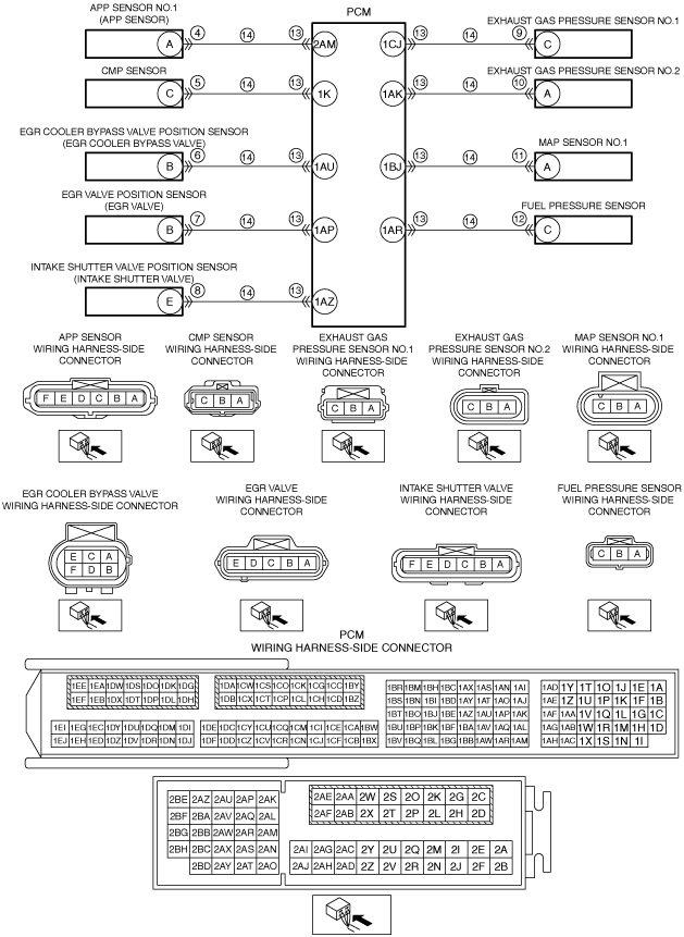
• Verify that the APP sensor, CMP sensor, EGR cooler bypass valve, EGR valve, intake shutter valve, exhaust gas pressure sensor No.1, exhaust gas pressure sensor No.2, MAP sensor No.1, fuel pressure sensor and PCM connectors are disconnected.
• Switch the ignition ON (engine off).
-
Note
-
• Another DTC may be stored by the PCM detecting an open circuit.
• Measure the voltage at the following terminals (wiring harness-side):
-
― APP sensor terminal A
― CMP sensor terminal C
― EGR cooler bypass valve terminal B
― EGR valve terminal B
― Intake shutter valve terminal E
― Exhaust gas pressure sensor No.1 terminal C
― Exhaust gas pressure sensor No.2 terminal A
― MAP sensor No.1 terminal A
― Fuel pressure sensor terminal C
• Is the voltage 0 V?
|
Yes
|
Go to the next step.
|
|
No
|
Refer to the wiring diagram and verify whether or not there is a common connector between the following terminals:
• APP sensor terminal A—PCM terminal 2AM
• CMP sensor terminal C—PCM terminal 1K
• EGR cooler bypass valve terminal B—PCM terminal 1AU
• EGR valve terminal B—PCM terminal 1AP
• Intake shutter valve terminal E—PCM terminal 1AZ
• Exhaust gas pressure sensor No.1 terminal C—PCM terminal 1CJ
• Exhaust gas pressure sensor No.2 terminal A—PCM terminal 1AK
• MAP sensor No.1 terminal A—PCM terminal 1BJ
• Fuel pressure sensor terminal C—PCM terminal 1AR
If there is a common connector:
• Determine the malfunctioning part by inspecting the common connector and the terminal for corrosion, damage, or pin disconnection, and the common wiring harness for a short to power supply.
• Repair or replace the malfunctioning part.
If there is no common connector:
• Repair or replace the wiring harness which has a short to power supply.
Go to Step 15.
|
|
15
|
VERIFY DTC TROUBLESHOOTING COMPLETED
• Always reconnect all disconnected connectors.
• Clear the DTC from the PCM memory using the M-MDS.
• Switch the ignition ON (engine off) and wait for 30 s or more.
• Perform the DTC Reading Procedure.
• Is the same DTC present?
|
Yes
|
Repeat the inspection from Step 1.
• If the malfunction recurs, replace the PCM.
Go to the next step.
|
|
No
|
Go to the next step.
|
|
16
|
VERIFY AFTER REPAIR PROCEDURE
• Perform the “AFTER REPAIR PROCEDURE”.
• Are any DTCs present?
|
Yes
|
Go to the applicable DTC inspection.
|
|
No
|
DTC troubleshooting completed.
|