 |
am6zzw00010381
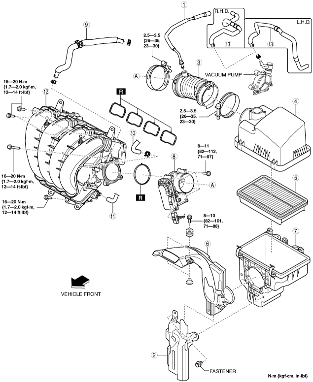
INTAKE-AIR SYSTEM REMOVAL/INSTALLATION [SKYACTIV-G 2.0, SKYACTIV-G 2.5]
id0113z9801900
1. Disconnect the negative battery cable. (See NEGATIVE BATTERY CABLE DISCONNECTION/CONNECTION [SKYACTIV-G 2.0, SKYACTIV-G 2.5].) (See NEGATIVE BATTERY CABLE DISCONNECTION/CONNECTION [SKYACTIV-G 2.0, SKYACTIV-G 2.5 (WITHOUT i-stop)].)
2. Remove in the order indicated in the table.
3. Install in the reverse order of removal.
am6zzw00010381
|
|
1
|
Ventilation hose
|
|
2
|
Resonance chamber
|
|
3
|
Air hose
|
|
4
|
Air cleaner cover
|
|
5
|
Air cleaner element
|
|
6
|
Fresh-air duct
(See Fresh-air Duct Removal Note.)
|
|
7
|
Air cleaner case
|
|
8
|
Throttle body
|
|
9
|
Vacuum hose (between intake manifold and vacuum pump)
(See Vacuum Hose Removal Note.)
|
|
10
|
Evaporative hose
|
|
11
|
PCV hose
|
|
12
|
Intake manifold
|
|
13
|
Vacuum hose (between vacuum pump and power brake unit)
|
Resonance Chamber Removal Note
1. Remove the MAF sensor/IAT sensor No.1. (See MASS AIR FLOW (MAF) SENSOR/INTAKE AIR TEMPERATURE (IAT) SENSOR NO.1 REMOVAL/INSTALLATION [SKYACTIV-G 2.0, SKYACTIV-G 2.5].)
2. Remove the following parts as a single unit:
3. Remove the resonance chamber.
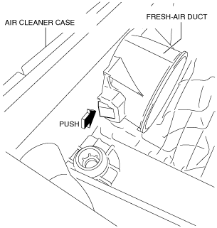
Fresh-air Duct Removal Note
1. Pull out the fresh-air duct while pressing the tab shown in the figure.
ac5uuw00000365
|
Vacuum Hose Removal Note
1. Remove the plug hole plate. (See PLUG HOLE PLATE REMOVAL/INSTALLATION [SKYACTIV-G 2.0, SKYACTIV-G 2.5].)
2. Remove the vacuum hose.
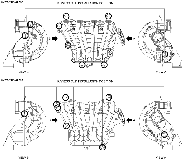
Intake Manifold Removal Note
1. Remove the MAP sensor/IAT sensor No.2. (See MANIFOLD ABSOLUTE PRESSURE (MAP) SENSOR/INTAKE AIR TEMPERATURE (IAT) SENSOR NO.2 REMOVAL/INSTALLATION [SKYACTIV-G 2.0, SKYACTIV-G 2.5].)
2. Disconnect the harness clip from the intake manifold as shown in the figure.
am6zzw00010382
|
3. Remove the intake manifold.
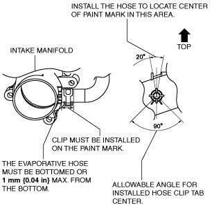
Evaporative Hose Installation Note
1. Install the evaporative hose as shown in the figure.
ac5wzw00002699
|
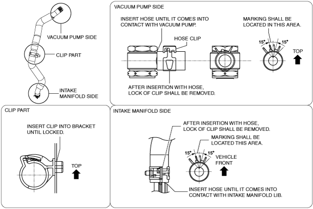
Vacuum Hose Installation Note
1. Install the vacuum hose as shown in the figure.
ac5wzw00002700
|
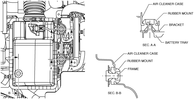
Air Cleaner Case Installation Note
1. Install the air cleaner case as shown in the figure.
ac5uuw00000367
|
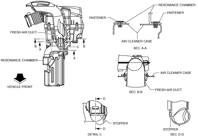
Fresh-air Duct Installation Note
1. Install the fresh-air duct as shown in the figure.
am6zzw00010383
|
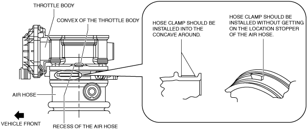
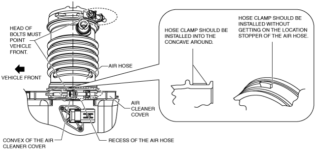
Air Hose Installation Note
1. Install the air hose as shown in the figure.
Throttle body side
am6zzw00013102
|
Air cleaner side
am6zzw00013103
|
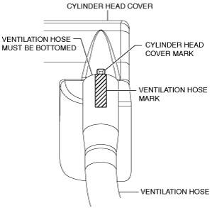
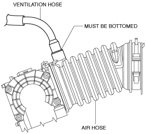
Ventilation Hose Installation Note
1. Install the ventilation hose as shown in the figure.
Cylinder head cover side
am3uuw00008002
|
Air hose side
ac5uuw00000371
|