 |
am6zzw00010441
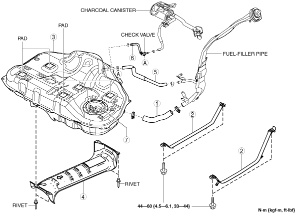
FUEL TANK REMOVAL/INSTALLATION [SKYACTIV-G 2.0, SKYACTIV-G 2.5]
id0114z9801600
1. Level the vehicle.
2. Complete the “BEFORE SERVICE PRECAUTION”. (See BEFORE SERVICE PRECAUTION [SKYACTIV-G 2.0, SKYACTIV-G 2.5].)
3. Drain the fuel. (See FUEL DRAINING PROCEDURE [SKYACTIV-G 2.0, SKYACTIV-G 2.5].)
4. Remove the rear seat cushion. (See REAR SEAT CUSHION REMOVAL/INSTALLATION.)
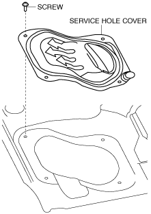
5. Remove the service hole cover.
am6zzw00010441
|
6. Disconnect the following parts:
7. Remove the floor under cover. (See FLOOR UNDER COVER REMOVAL/INSTALLATION.)
8. Disconnect the HO2S connector.
9. Remove the TWC and HO2S as a single unit. (See EXHAUST SYSTEM REMOVAL/INSTALLATION [SKYACTIV-G 2.0, SKYACTIV-G 2.5].)
10. Remove in the order indicated in the table.
11. Install in the reverse order of removal.
12. Complete the “AFTER SERVICE PRECAUTION”. (See AFTER SERVICE PRECAUTION [SKYACTIV-G 2.0, SKYACTIV-G 2.5].)
am6zzw00010442
|
|
1
|
Joint hose
(See Joint Hose Installation Note.)
|
|
2
|
Fuel tank strap
|
|
3
|
Fuel tank
(See Fuel Tank Removal Note.)
|
|
4
|
Fuel tank insulator
|
|
5
|
Breather hose
|
|
6
|
Evaporative hose
|
|
7
|
Fuel pump unit
|
Fuel Tank Removal Note
1. Disconnect the breather hose from the fuel-filler pipe side.
2. Disconnect the evaporative hose (between charcoal canister and check valve) from the check valve side.
3. Remove the following parts as single unit:
4. Remove the fuel tank.
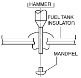
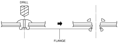
Fuel Tank Insulator Removal Note
1. Push out the mandrel using a hammer and punch (2—2.8 mm {0.08—0.11 in} diameter).
ac5wzw00002710
|
2. Remove the flange using a drill (5 mm {0.20 in} drill bit).
ar8uuw00001479
|
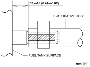
Evaporative Hose Installation Note
1. Install the evaporative hose as shown in the figure.
am6zzw00010443
|
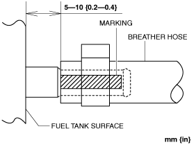
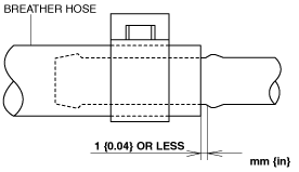
Breather Hose Installation Note
1. Install the breather hose as shown in the figure.
Fuel tank side
am6zzw00010444
|
Fuel-filler pipe side
am6zzw00010445
|
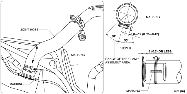
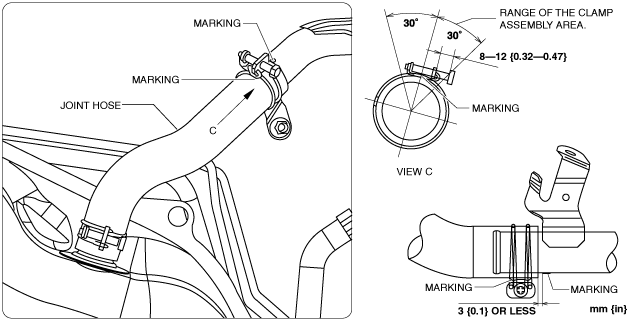
Joint Hose Installation Note
1. Install the joint hose as shown in the figure.
Fuel tank side
am6zzw00010446
|
Fuel-filler pipe side
am6zzw00010447
|