 |
ac5uun00001136
FUEL PUMP CONTROL [SKYACTIV-G 2.0, SKYACTIV-G 2.5]
id0140g2004100
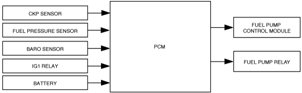
Outline
Block Diagram
ac5uun00001136
|
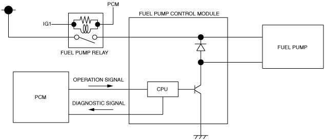
Operation
Fuel pump relay
|
Relay ON/OFF |
Control conditions |
|---|---|
|
ON
|
• When any of the following conditions is met:
|
|
OFF
|
• When engine is stopped (excludes engine stop by i-stop control)
• Immobilizer system related information (engine start prohibited) received from start stop unit
• Collision signal from SAS control module is received
|
Fuel pump control module
|
Output duty ratio |
Control conditions |
|---|---|
|
95%
|
• When any of the following conditions is met:
|
|
10—90%
|
• Except for control conditions with output duty ratio of 5% or 95%
|
|
5%
|
• When engine is stopped by i-stop control
|
Fuel pump operation circuit diagram
am3zzn00003420
|