 |
ac5wzn00001579
FUEL INJECTION CONTROL SYSTEM [SKYACTIV-G 2.0, SKYACTIV-G 2.5]
id0140g2138600
Outline
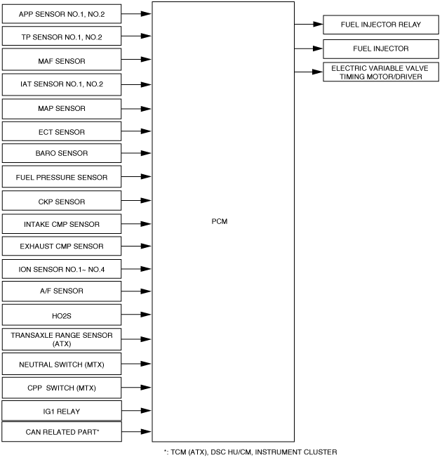
Block Diagram
ac5wzn00001579
|
Operation
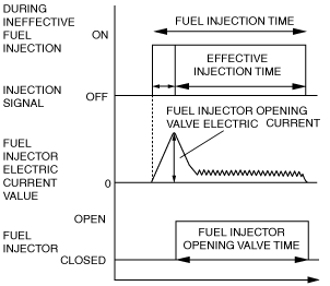
Injection timing
Injection time
ac5uun00001135
|
Determination of effective injection time
am6zzn00002915
|
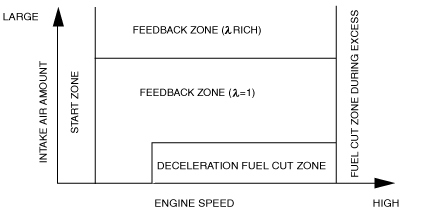
Control zone table
|
Control name |
Control outline |
|---|---|
|
Start zone
|
Purpose
• Improved startability
Control condition
• When engine speed is less than 500 rpm
Determination of fuel injection time
• According to engine coolant temperature and engine speed and fuel pressure
|
|
Feedback zone (λ= 1)
|
Purpose
• Improved fuel economy
• Improved exhaust gas purification
Control condition
• During engine operation condition except for engine start zone and feedback zone (λ rich) and fuel cut zone
Determination of fuel injection time
• During normal driving, the various correction amounts are added to the basic injection time during normal driving to obtain a ratio that is close to the theoretical air/fuel ratio.
|
|
Feedback zone (λ rich)
|
Purpose
• Improved driveability
Control condition
• The accelerator pedal opening angle is the specified value or more
Determination of fuel injection time
• Fuel amount increases according to accelerator pedal opening angle
|
|
Purpose
• Protection of catalytic converter and exhaust system components (suppression of gas temperature)
Control condition
• The estimated exhaust temperature and estimated catalytic converter temperature are the specified value or more.
Determination of fuel injection time
• Fuel amount increases according to estimated exhaust gas temperature and estimated catalytic converter temperature (promotion of cooling efficiency from vaporization heat)
|
|
|
Excessive speed fuel cut zone
|
Purpose
• Engine protection
Control condition
• When engine speed is 6,800 rpm or more (SKYACTIV-G 2.0)
• When engine speed is 6,500 rpm or more (SKYACTIV-G 2.5)
• When engine speed is 2,500 rpm or more (When DTC P0089:00 is stored)
Determination of fuel injection time
• Fuel injection stopped.
|
|
Deceleration fuel cut zone
|
Purpose
• Improved fuel economy
Control condition
• If all of the following conditions are met while the vehicle is decelerating
Determination of fuel injection time
• Fuel injection is stopped.
|
Fuel injection time calculation method table
|
Contents
(Calculation or determination method for fuel injection time and correction)
|
Control zone
|
||||||
 |
 |
 |
 |
 |
|||
|
Injection time at engine start
|
Set value according to engine coolant temperature (low engine coolant temperature→long injection time)
|
A
|
|
|
|
|
|
|
Basic injection time
|
Basic injection time = Charging efficiency *1× fuel flow coefficient*2
|
|
A
|
A
|
|
|
|
|
Fuel cut
|
Fuel injection time = 0
|
|
|
|
A
|
A
|
|
|
Ineffective injection time
|
Set time according to fuel injector performance
|
A
|
A
|
A
|
|
|
|
|
Volume increase correction at engine start
|
Purpose: Ensures engine speed stability just after engine start
Correction condition
• Specified time according to engine coolant temperature directly after engine start
Correction amount
• Low engine coolant temperature→large correction
• Low intake air temperature→large correction
|
B
|
B
|
|
|
|
|
|
Feedback correction (A/F sensor)
|
Purpose: Controls air/fuel ratio to theoretical air/fuel ratio
Correction amount
• A/F sensor output current is 0 mA or less→volume decrease correction
• A/F sensor output current is 0 mA or more→volume increase correction
|
|
B
|
B
|
|
|
|
|
Feedback correction (HO2S)
|
Purpose: Controls air/fuel ratio to theoretical air/fuel ratio
Correction amount
• HO2S output voltage is approx. 0.7 V or more→volume decrease correction
• HO2S output voltage is approx. 0.7 V or less→volume increase correction
|
|
B
|
|
|
|
|
|
Warm-up volume increase correction
|
Purpose: Ensures combustion stability when engine coolant temperature is low
Correction condition
• When engine coolant temperature is at set value
Correction amount
• High charging efficiency, low engine coolant temperature→large correction
|
|
B
|
B
|
|
|
|
|
Learning correction
|
Purpose: Corrects deviation in air/fuel ratio from deterioration over time of mechanical devices
Correction amount
• Learned value based on average value of A/F deviation amount (feedback amount)
|
|
B
|
B
|
|
|
|
|
Heavy load volume increase correction
|
Purpose: Improved engine output, decrease of exhaust gas temperature
Correction condition
• Based on the fixed value when the accelerator pedal opening angle is a certain value or more, otherwise, based on engine speed and charging efficiency.
Correction amount
• High engine speed, high charging efficiency→large correction
|
|
|
B
|
|
|
|
Fuel cut
Fuel cut table
|
Control name |
Control outline |
|---|---|
|
Fuel cut during selector lever shifting in D range (ATX)
|
Purpose
• ATX protection
Control conditions
• When shifting while vehicle is stopped and engine raced
|
|
Sensor malfunction fuel cut
|
Purpose
• To prevent engine damage from abnormal ignition due to a malfunction input of a cylinder identification or the engine speed signal.
Control conditions
• When a malfunction in the crankshaft position sensor or exhaust camshaft position sensor is detected
|
|
Dechoke control
|
Purpose
• To improve engine startability when spark plugs are flooded (scavenging)
Control conditions
• When cranking close to fully-open throttle valve
|
|
Theft prevention
|
Purpose
• To prevent theft
Control conditions
• Immobilizer system related information (engine start prohibited) received from start stop unit
|
|
Fuel-cut at time of collision
|
Purpose
• For safety assurance
Control conditions
• Collision signal from SAS control module is received
|
Boost Circuit
Output Circuit
|
Fuel injector status |
PCM operation |
|---|---|
|
Opening starts
|
1. Provides specified value, boosted by the boost circuit, to the opening transistor.
2. Voltage is provided to the fuel injector, the ground transistor is turned on and grounded, and the fuel injector opens.
3. After the fuel injector is opened, the opening transistor is turned off.
|
|
Opening held
|
• Controls the on/off of the holding transistor (12 V output) so that the hold current of the fuel injector is constant.
|
|
Closing
|
• Turns off the holding and ground transistors at the same time the fuel injection signal from the PCM is stopped, and cuts the current.
|