CRANKSHAFT POSITION (CKP) SENSOR INSPECTION [SKYACTIV-G 2.0, SKYACTIV-G 2.5]
id0140g2800500
Visual Inspection
-
Caution
-
• When foreign material such as an iron chip is on the CKP sensor, it can cause abnormal output from the sensor because of flux turbulence and adversely affect the engine control. Be sure there is no foreign material on the CKP sensor when replacing.
1. Disconnect the negative battery cable. (See NEGATIVE BATTERY CABLE DISCONNECTION/CONNECTION [SKYACTIV-G 2.0, SKYACTIV-G 2.5].) (See NEGATIVE BATTERY CABLE DISCONNECTION/CONNECTION [SKYACTIV-G 2.0, SKYACTIV-G 2.5 (WITHOUT i-stop)].)
2. Lift up the vehicle.
3. Perform the following procedure for easier access.
- (1) Remove the service hole cover (installed to front under cover No.2) used to remove the oil filter. (See OIL FILTER REPLACEMENT [SKYACTIV-G 2.0, SKYACTIV-G 2.5].)
- (2) Remove the front splash shield. (See SPLASH SHIELD REMOVAL/INSTALLATION.)
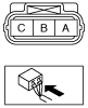
4. Disconnect the CKP sensor connector.
5. Remove the CKP sensor. (See CRANKSHAFT POSITION (CKP) SENSOR REMOVAL/INSTALLATION [SKYACTIV-G 2.0, SKYACTIV-G 2.5].)
6. Verify that there are no metal shavings on the sensor.
-
• If there is a malfunction, remove any metal shavings that are adhering.
Voltage Inspection
-
Caution
-
• When foreign material such as an iron chip is on the CKP sensor, it can cause abnormal output from the sensor because of flux turbulence and adversely affect the engine control. Be sure there is no foreign material on the CKP sensor when replacing.
• If the wiring harnesses or waterproof connectors are damaged, water penetrating the connector will cause a sensor malfunction. To prevent this, be careful not to damage wiring harnesses or waterproof connectors.
1. Idle the engine.
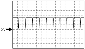
2. Measure the CKP sensor output voltage wave pattern using an oscilloscope.
-
-
• Specification
-
4.5 V or more (Maximum value of wave pattern)
0.8 V or less (Minimum value of wave pattern)
Wave pattern (reference)
Oscilloscope setting
-
• 2 V/DIV (Y), 1 ms/DIV (X), DC range
Vehicle condition
-
• Idle (after warm up)