PCM REMOVAL/INSTALLATION [SKYACTIV-G 2.0, SKYACTIV-G 2.5]
id0140g2802400
-
Caution
-
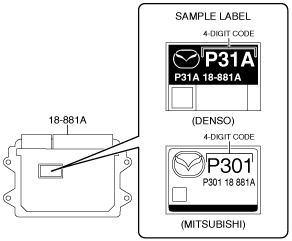
• There are two types of PCM settings. If the incorrect PCM is installed, it could cause interference with engine control.
• When replacing the PCM, verify the first four digits of the part number indicated on the PCM label before replacement, and replace the PCM with one having the same part number.
• If configuration is not performed when the PCM is replaced with a new one, the vehicle specification information is not stored in the PCM and the system will not operate normally.
• When performing configuration, it is necessary to read the vehicle specification information from the PCM before replacing it. Connect the M-MDS to the vehicle and perform vehicle identification before removing the PCM. The vehicle specification information is temporarily stored in the M-MDS.
-
Note
-
• The PCM prior to replacement stores the vehicle specification information.
• A new PCM does not store any vehicle specification information.
• If the vehicle specification information PCM prior to replacement cannot be read, perform the configuration using As-Built data.
Without Set Bolt
1. Disconnect the negative battery cable. (See NEGATIVE BATTERY CABLE DISCONNECTION/CONNECTION [SKYACTIV-G 2.0, SKYACTIV-G 2.5].) (See NEGATIVE BATTERY CABLE DISCONNECTION/CONNECTION [SKYACTIV-G 2.0, SKYACTIV-G 2.5 (WITHOUT i-stop)].)
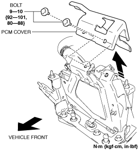
2. Remove the PCM cover. (See PCM Cover Installation Note.)
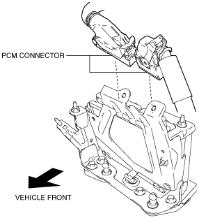
3. Disconnect the PCM connector. (See PCM Connector Connection Note.)
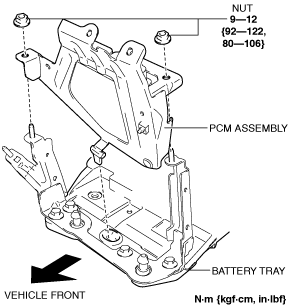
4. Remove the PCM assembly from the battery tray. (See PCM Assembly Installation Note.)
5. Remove the PCM from the PCM bracket.
6. Install in the reverse order of removal.
7. When replacing the PCM on the vehicles, perform the following:
-
Note
-
-
With Set Bolt
1. Disconnect the negative battery cable. (See NEGATIVE BATTERY CABLE DISCONNECTION/CONNECTION [SKYACTIV-G 2.0, SKYACTIV-G 2.5].) (See NEGATIVE BATTERY CABLE DISCONNECTION/CONNECTION [SKYACTIV-G 2.0, SKYACTIV-G 2.5 (WITHOUT i-stop)].)
2. Remove the PCM cover. (See PCM Cover Installation Note.) (See Set Bolt Removal Note.) (See Set Bolt Installation Note.)
3. Disconnect the PCM connector. (See PCM Connector Connection Note.)
4. Remove the PCM assembly from the battery tray. (See PCM Assembly Installation Note.)
5. Remove the PCM from the PCM bracket.
6. Install in the reverse order of removal.
7. When replacing the PCM on the vehicles, perform the following:
-
Note
-
-
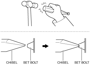
Set Bolt Removal Note
1. Using a chisel and a hammer, cut a groove on the head of the set bolt so that a screwdriver can be inserted.
2. Loose the set bolt using an impact screwdriver or pliers.
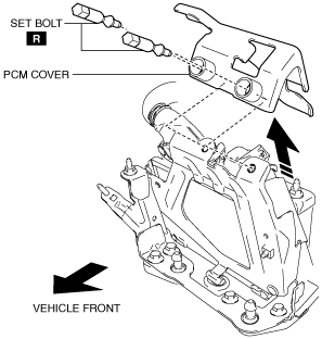
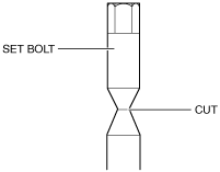
Set Bolt Installation Note
1. Install a new set bolt and tighten it until the neck of the bolt is cut.
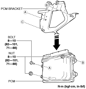
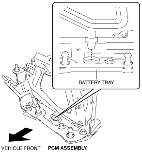
PCM Assembly Installation Note
1. Install the PCM assembly shown in the figure.
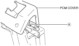
PCM Cover Installation Note
1. Insert the PCM cover end into area A shown in the figure.
2. Temporarily tighten the two bolts, then completely tighten them.
PCM Connector Connection Note
-
Caution
-
• Do not touch the PCM connector terminal. The terminal is extremely thin and can be damaged by touching it.
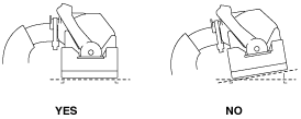
• If the PCM connector is inserted at an angle and the lever is moved, the connector could be damaged. Verify that the PCM connector is inserted straight.
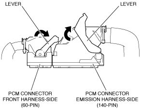
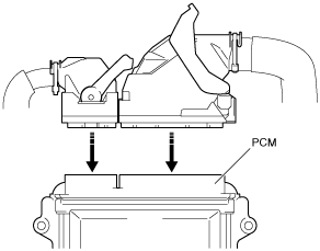
1. Set the PCM connector to the position shown in the figure.
2. Align the PCM connector straight against the connection surface.
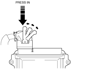
3. Insert the PCM connector straight and press it in until the lever moves up naturally. (Front harness-side connector)
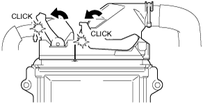
4. Press the PCM connector lever until a click sound is heard.