 |
ac5wzw00001000
REAR CROSSMEMBER REMOVAL/INSTALLATION [2WD]
id0214008010a1
1. Switch the ignition ON (engine off).
2. Release the electric parking brake.
3. Switch the ignition off.
4. Disconnect the negative battery cable. (See NEGATIVE BATTERY CABLE DISCONNECTION/CONNECTION [SKYACTIV-G 2.0, SKYACTIV-G 2.5].) (See NEGATIVE BATTERY CABLE DISCONNECTION/CONNECTION [SKYACTIV-G 2.0, SKYACTIV-G 2.5 (WITHOUT i-stop)].) (See NEGATIVE BATTERY CABLE DISCONNECTION/CONNECTION [SKYACTIV-D 2.2].)
5. Remove the wheels and tires. (See WHEEL AND TIRE REMOVAL/INSTALLATION.)
6. Disconnect the wiring harness clips and connector installed to the rear crossmember.
ac5wzw00001000
|
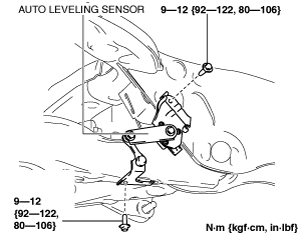
7. Remove the auto leveling sensor. (With auto leveling sensor) (See AUTO LEVELING SENSOR REMOVAL/INSTALLATION.)
am6zzw00008958
|
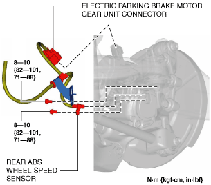
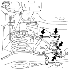
8. Disconnect the rear ABS wheel-speed sensor wiring harness and the electric parking brake motor gear unit connector and set it aside so that it does not interfere with the servicing. (See REAR ABS WHEEL-SPEED SENSOR REMOVAL/INSTALLATION [2WD].)
am6xuw00007612
|
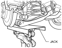
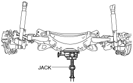
9. Jack up the vehicle to the unloaded condition, and support the rear trailing link component using a jack.
ac5wzw00002868
|
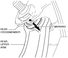
10. Align the rear crossmember component and rear upper arm and mark them.
ac5uuw00000186
|
11. Remove the TWC. (SKYACTIV-G 2.0, SKYACTIV-G 2.5) (See EXHAUST SYSTEM REMOVAL/INSTALLATION [SKYACTIV-G 2.0, SKYACTIV-G 2.5].)
12. Remove the middle pipe. (SKYACTIV-D 2.2) (See EXHAUST SYSTEM REMOVAL/INSTALLATION [SKYACTIV-D 2.2].)
13. Remove the rear lateral link. (See REAR LATERAL LINK REMOVAL/INSTALLATION.)
14. Remove the rear coil spring. (See REAR COIL SPRING REMOVAL/INSTALLATION.)
15. Remove the rear lower arm. (See REAR LOWER ARM REMOVAL/INSTALLATION.)
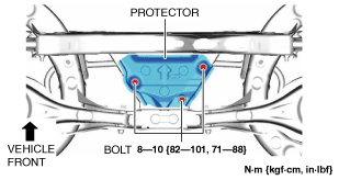
16. Remove the protector. (With SKYACTIV-G 2.0,SKYACTIV-G 2.5 )
ac4ccw00000689
|
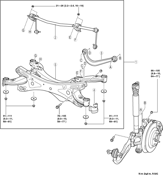
17. Remove in the order indicated in the table).
18. Install in the reverse order of removal. (See Suspension Links Installation Note.)
19. Inspect the wheel alignment and adjust it if necessary. (See REAR WHEEL ALIGNMENT.)
am6zzw00014908
|
|
1
|
Rear crossmember component
|
|
2
|
Rear stabilizer component
|
|
3
|
Rear upper arm
|
|
4
|
Rear crossmember mudguard
|
|
5
|
Rear crossmember
|
Rear Crossmember Component Removal Note
1. Support the rear crossmember with the jack and remove the nuts
ac5uuw00000188
|
2. Remove the rear crossmember component.
Suspension Links Installation Note
1. When installing the joint sections with rubber bushings, perform the following procedures.
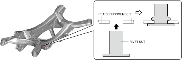
Rear Crossmember Installation Note
1. When replacing the rear crossmember, install the rivet nut using a rivet nut tool.
am6zzw00014684
|
Rear Crossmember Component Installation Note
1. Support the rear crossmember component and install the rear crossmember.
ac5uuw00000188
|