 |
am6zzw00014703
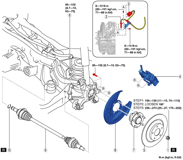
REAR DRIVE SHAFT REMOVAL/INSTALLATION
id031300800600
1. Switch the ignition ON (engine off).
2. Release the electric parking brake.
3. Switch the ignition off.
4. Disconnect the negative battery cable. (See NEGATIVE BATTERY CABLE DISCONNECTION/CONNECTION [SKYACTIV-D 2.2].)
5. Remove the wheel and tire. (See WHEEL AND TIRE REMOVAL/INSTALLATION.)
6. Drain the rear differential oil into a container. (See DIFFERENTIAL OIL REPLACEMENT.)
7. Remove in the order indicated in the table.
8. Install in the reverse order of removal.
9. After installation, add the specified rear differential oil. (See DIFFERENTIAL OIL REPLACEMENT.)
am6zzw00014703
|
|
1
|
Locknut
(See Locknut Removal Note.)
(See Locknut Installation Note.)
|
|
2
|
Rear ABS wheel-speed sensor
|
|
3
|
Electric parking brake motor gear unit connector
|
|
4
|
Brake caliper component
|
|
5
|
Disc plate
|
|
6
|
Bolt (wheel hub)
|
|
7
|
Wheel hub
(See Wheel Hub Removal Note.)
|
|
8
|
Dust cover
|
|
9
|
Rear drive shaft
|
|
10
|
Rear drive shaft clip
|
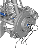
Locknut Removal Note
1. Remove the locknut with the brake pedal depressed.
2. Install a spare nut onto the drive shaft.
3. Tap the nut with a copper hammer and separate the drive shaft from the axle.
am6zzw00015572
|
Wheel Hub Removal Note
1. Before removing the wheel hub, place alignment marks on the wheel hub and the hub support so that they can be installed to the same position before removal.
2. Remove the wheel hub.
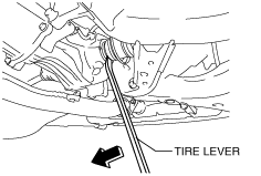
Rear Drive Shaft Removal Note
1. Insert a tire lever or equivalent tool between the rear differential-side outer ring and the rear differential.
ac5uuw00004755
|
2. Move the tire lever or the equivalent in the direction of the arrow shown in the figure and detach the rear differential and the rear drive shaft.
3. Remove the rear drive shaft by pulling it to the wheel side until it is removed from the differential.
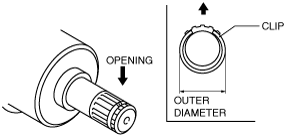
Rear Drive Shaft Clip Installation Note
1. Install a new clip to the clip groove at the end of the rear drive shaft with the clip opening facing upward.
ac5wzw00002574
|
2. Verify that the outer diameter of the clip is within the specification.
Rear Drive Shaft Installation Note
1. Apply rear differential oil to the oil seal lip.
2. Insert the rear drive shaft to the wheel hub component.
3. Install the rear drive shaft to the rear differential.
4. After installation, verify that the rear drive shaft is securely held by the clip by pulling the outer ring on the rear differential side towards the axle side.
Locknut Installation Note
1. If dust or grease is on the drive shaft thread area, wipe it off with a cloth.
2. Tighten the locknut using the following procedure and with the brake pedal depressed.