 |
am6zzn00003363
ON-BOARD DIAGNOSTIC SYSTEM [DYNAMIC STABILITY CONTROL (DSC)]
id0402b2181300
OUTLINE
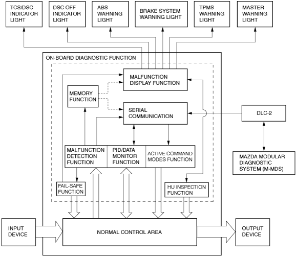
Block diagram
am6zzn00003363
|
FUNCTION
Malfunction detection function
Memory function
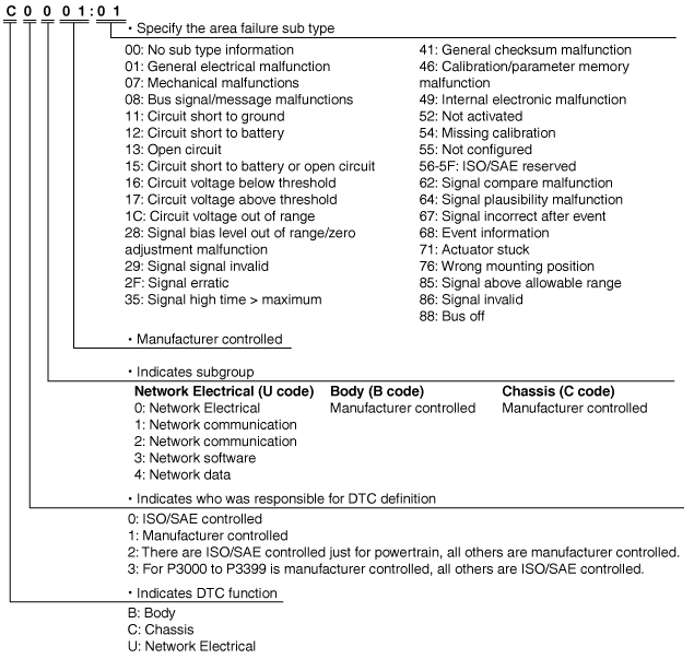
DTC 7-digit code definition
ac5wzn00001215
|
Fail-safe function
|
DTC No. |
ABS warning light |
Brake system warning light (when parking brake is released) |
TCS/DSC indicator light |
DSC OFF indicator light |
Tire pressure monitoring system warning light |
Master warning light*1*2 |
Malfunction location |
Fail-safe |
Drive cycle |
Self test type*3 |
Memory function |
|---|---|---|---|---|---|---|---|---|---|---|---|
|
B11D4:08*2
|
Not illuminated
|
Not illuminated
|
Not illuminated
|
Not illuminated
|
Not illuminated
|
Illuminated
|
Laser sensor
|
×
|
Not applicable
|
C, D
|
×
|
|
C0001:01
|
Illuminated
|
Illuminated
|
Illuminated
|
Not illuminated
|
Not illuminated
|
Illuminated
|
DSC HU/CM internal malfunction (solenoid valve system)
|
×
|
Not applicable
|
C, D
|
×
|
|
C0003:01
|
|||||||||||
|
C0010:01
|
|||||||||||
|
C0011:01
|
|||||||||||
|
C0014:01
|
|||||||||||
|
C0015:01
|
|||||||||||
|
C0018:01
|
|||||||||||
|
C0019:01
|
|||||||||||
|
C001C:01
|
|||||||||||
|
C001D:01
|
|||||||||||
|
C0020:01
|
Illuminated
|
Illuminated
|
Illuminated
|
Not illuminated
|
Not illuminated
|
Illuminated
|
Pump motor, motor relay
|
×
|
Not applicable
|
C, D
|
×
|
|
C0020:11
|
|||||||||||
|
C0020:13
|
|||||||||||
|
C0020:16
|
|||||||||||
|
C0020:1C
|
|||||||||||
|
C0020:71
|
|||||||||||
|
C0023:62*1*2
|
Not illuminated
|
Not illuminated
|
Not illuminated
|
Not illuminated
|
Not illuminated
|
Illuminated
|
Brake light/Brake switch
|
×
|
Not applicable
|
C, D
|
×
|
|
C0031:01
|
Illuminated
|
Not illuminated*4
|
Illuminated
|
Not illuminated
|
Flashes*8
|
Illuminated
|
LF ABS wheel-speed sensor
|
×
|
Not applicable
|
C, D
|
×
|
|
C0031:13
|
|||||||||||
|
C0031:23
|
Illuminated
|
Not illuminated*4
|
Illuminated
|
Not illuminated
|
Flashes*8
|
Illuminated
|
LF ABS wheel-speed sensor/ABS sensor rotor
|
×
|
Not applicable
|
C, D
|
×
|
|
C0031:27
|
|||||||||||
|
C0034:01
|
Illuminated
|
Not illuminated*4
|
Illuminated
|
Not illuminated
|
Flashes*8
|
Illuminated
|
RF ABS wheel-speed sensor
|
×
|
Not applicable
|
C, D
|
×
|
|
C0034:13
|
|||||||||||
|
C0034:23
|
Illuminated
|
Not illuminated*4
|
Illuminated
|
Not illuminated
|
Flashes*8
|
Illuminated
|
RF ABS wheel-speed sensor/ABS sensor rotor
|
×
|
Not applicable
|
C, D
|
×
|
|
C0034:27
|
|||||||||||
|
C0037:01
|
Illuminated
|
Not illuminated*4
|
Illuminated
|
Not illuminated
|
Flashes*8
|
Illuminated
|
LR ABS wheel-speed sensor
|
×
|
Not applicable
|
C, D
|
×
|
|
C0037:13
|
|||||||||||
|
C0037:23
|
Illuminated
|
Not illuminated*4
|
Illuminated
|
Not illuminated
|
Flashes*8
|
Illuminated
|
LR ABS wheel-speed sensor/ABS sensor rotor
|
×
|
Not applicable
|
C, D
|
×
|
|
C0037:27
|
|||||||||||
|
C0037:62
|
Illuminated
|
||||||||||
|
C003A:01
|
Illuminated
|
Not illuminated*4
|
Illuminated
|
Not illuminated
|
Flashes*8
|
Illuminated
|
RR ABS wheel-speed sensor
|
×
|
Not applicable
|
C, D
|
×
|
|
C003A:13
|
|||||||||||
|
C003A:23
|
Illuminated
|
Not illuminated*4
|
Illuminated
|
Not illuminated
|
Flashes*8
|
Illuminated
|
RR ABS wheel-speed sensor/ABS sensor rotor
|
×
|
Not applicable
|
C, D
|
×
|
|
C003A:27
|
|||||||||||
|
C003A:62
|
Illuminated
|
Flashes*8
|
|||||||||
|
C0040:64
|
Illuminated
|
Not illuminated
|
Illuminated
|
Not illuminated
|
Flashes*8
|
Illuminated
|
Brake light/Brake switch
|
×
|
Not applicable
|
C, D
|
×
|
|
C0040:86
|
|||||||||||
|
C0044:14
|
Not illuminated
|
Not illuminated
|
Illuminated
|
Not illuminated
|
Flashes*8
|
Illuminated
|
Brake fluid pressure sensor
|
×
|
Not applicable
|
C, D
|
×
|
|
C0044:1C
|
|||||||||||
|
C0044:65
|
|||||||||||
|
C0044:66
|
|||||||||||
|
C0044:67
|
|||||||||||
|
C0051:28
|
Not illuminated
|
Not illuminated
|
Illuminated
|
Not illuminated
|
Not illuminated
|
Illuminated
|
EPS control module
|
×
|
Not applicable
|
C, D
|
×
|
|
C0051:67
|
|||||||||||
|
C0061:27
|
Illuminated
|
Not illuminated
|
Illuminated
|
Not illuminated
|
Flashes*8
|
Illuminated
|
SAS control module system (lateral-G signal)
|
×
|
Not applicable
|
C, D
|
×
|
|
C0061:28
|
|||||||||||
|
C0061:29
|
|||||||||||
|
C0061:54
|
Illuminated
|
Not illuminated
|
Illuminated
|
Not illuminated
|
Flashes*8
|
Illuminated
|
DSC HU/CM system (unperformed initialization procedure)
|
×
|
Not applicable
|
C, D
|
×
|
|
C0061:62
|
Not illuminated
|
Not illuminated
|
Illuminated
|
Not illuminated
|
Flashes*8
|
Illuminated
|
SAS control module system
|
×
|
Not applicable
|
C, D
|
×
|
|
C0062:27
|
Illuminated
|
Not illuminated
|
Illuminated
|
Not illuminated
|
Not illuminated
|
Illuminated
|
SAS control module system
|
||||
|
C0062:28
|
|||||||||||
|
C0062:29
|
|||||||||||
|
C0062:54
|
Illuminated
|
Not illuminated
|
Illuminated
|
Not illuminated
|
Not illuminated
|
Illuminated
|
DSC HU/CM system (unperformed initialization procedure)
|
×
|
Not applicable
|
C, D
|
×
|
|
C0062:62
|
Illuminated
|
Not illuminated
|
Illuminated
|
Not illuminated
|
Not illuminated
|
Illuminated
|
SAS control module system
|
×
|
Not applicable
|
C, D
|
×
|
|
C0062:65
|
|||||||||||
|
C0063:27
|
Not illuminated
|
Not illuminated
|
Illuminated
|
Not illuminated
|
Flashes*8
|
Illuminated
|
SAS control module system
|
||||
|
C0063:28
|
|||||||||||
|
C0063:29
|
|||||||||||
|
C0063:54
|
Not illuminated
|
Not illuminated
|
Illuminated
|
Not illuminated
|
Flashes*8
|
Illuminated
|
DSC HU/CM system (unperformed initialization procedure)
|
×
|
Not applicable
|
C, D
|
×
|
|
C0063:61
|
Not illuminated
|
Not illuminated
|
Illuminated
|
Not illuminated
|
Flashes*8
|
Illuminated
|
SAS control module system
|
×
|
Not applicable
|
C, D
|
×
|
|
C0063:62
|
|||||||||||
|
C006A:61
|
Illuminated
|
Not illuminated
|
Illuminated
|
Not illuminated
|
Flashes*4*8
|
Illuminated
|
|||||
|
C0089:64
|
Not illuminated
|
Not illuminated
|
Not illuminated
|
Not illuminated
|
Not illuminated
|
Not illuminated
|
DSC OFF switch
|
Not applicable
|
Not applicable
|
C, D
|
×
|
|
C1031:35
|
Not illuminated
|
Not illuminated
|
Not illuminated
|
Not illuminated
|
Flashes*8
|
Not illuminated
|
Tire Pressure Monitoring System (TPMS) set switch
|
×
|
Not applicable
|
C, D
|
×
|
|
C1031:54
|
Not illuminated
|
Not illuminated
|
Not illuminated
|
Not illuminated
|
Flashes*8
|
Not illuminated
|
Tire Pressure Monitoring System (TPMS) system
|
×
|
Not applicable
|
C, D
|
×
|
|
C1031:68
|
Not illuminated
|
Not illuminated
|
Not illuminated
|
Not illuminated
|
Flashes*8
|
Not illuminated
|
Tire Pressure Monitoring System (TPMS) system
|
×
|
Not applicable
|
C, D
|
×
|
|
C1A77:12
|
Illuminated
|
Illuminated
|
Illuminated
|
Not illuminated
|
Not illuminated
|
Illuminated
|
Solenoid valve relay
|
×
|
Not applicable
|
C, D
|
×
|
|
C1A77:13
|
|||||||||||
|
C1A77:16
|
|||||||||||
|
U0001:88
|
Illuminated
|
Not illuminated
|
Illuminated
|
Not illuminated
|
Flashes*8
|
Illuminated
|
CAN line
|
×
|
Not applicable
|
C, D
|
×
|
|
U0100:00
|
Illuminated*5
|
Illuminated*5
|
Flashes*4*8
|
||||||||
|
U0101:00*6
|
Not illuminated
|
Illuminated
|
Not illuminated
|
||||||||
|
U0104:00*1
|
Not illuminated
|
||||||||||
|
U0114:00*7
|
Not illuminated
|
Not illuminated
|
|||||||||
|
U0131:00
|
Illuminated
|
Illuminated
|
|||||||||
|
U0154:00
|
Not illuminated
|
Not illuminated
|
Illuminated
|
Not illuminated
|
Not illuminated
|
Not illuminated
|
CAN line
|
×
|
Not applicable
|
C, D
|
×
|
|
U0154:87
|
Illuminated
|
Not illuminated
|
Illuminated
|
Flashes*8
|
Illuminated
|
||||||
|
U0155:00
|
Not illuminated
|
Illuminated*5
|
Not illuminated
|
Not illuminated
|
Illuminated*5
|
||||||
|
U0214:00*1
|
Not illuminated
|
Not illuminated
|
|||||||||
|
U023A:00*2
|
|||||||||||
|
U0301:00*1
|
Illuminated
|
Illuminated
|
Illuminated*5
|
Illuminated
|
Flashes*4*8
|
Illuminated*5
|
Abnormal message from PCM
|
×
|
Not applicable
|
C, D
|
×
|
|
U0305:00*1
|
Not illuminated
|
Not illuminated
|
Not illuminated
|
Not illuminated
|
Not illuminated
|
Illuminated
|
Abnormal message from radar unit
|
×
|
Not applicable
|
C, D
|
×
|
|
U0320:00
|
Not illuminated
|
Not illuminated
|
Illuminated
|
Not illuminated
|
Not illuminated
|
Illuminated
|
Abnormal message from EPS control module
|
×
|
Not applicable
|
C, D
|
×
|
|
U0323:00*2
|
Not illuminated
|
Not illuminated
|
Illuminated
|
Not illuminated
|
Not illuminated
|
Illuminated
|
Abnormal message from instrument cluster
|
×
|
Not applicable
|
C, D
|
×
|
|
U0336:00
|
Not illuminated
|
Not illuminated
|
Illuminated
|
Not illuminated
|
Not illuminated
|
Not illuminated
|
Abnormal message from SAS control module
|
×
|
Not applicable
|
C, D
|
×
|
|
U0338:00*1
|
Not illuminated
|
Not illuminated
|
Not illuminated
|
Not illuminated
|
Not illuminated
|
Not illuminated
|
Abnormal message from start stop unit
|
×
|
Not applicable
|
C, D
|
×
|
|
U0401:00
|
Not illuminated
|
Not illuminated
|
Illuminated*5
|
Not illuminated
|
Not illuminated
|
Illuminated*5
|
Abnormal message from PCM
|
×
|
Not applicable
|
C, D
|
×
|
|
U0402:00*6
|
Not illuminated
|
Not illuminated
|
Illuminated
|
Not illuminated
|
Not illuminated
|
Illuminated
|
Abnormal message from TCM
|
×
|
Not applicable
|
C, D
|
×
|
|
U0403:00*7
|
Not illuminated
|
Not illuminated
|
Not illuminated
|
Not illuminated
|
Not illuminated
|
Not illuminated
|
Abnormal message from 4WD control module
|
×
|
Not applicable
|
C, D
|
×
|
|
U0405:00*1
|
Not illuminated
|
Not illuminated
|
Not illuminated
|
Not illuminated
|
Not illuminated
|
Illuminated
|
Abnormal message from radar unit
|
×
|
Not applicable
|
C, D
|
×
|
|
U0420:00
|
Not illuminated
|
Not illuminated
|
Illuminated
|
Not illuminated
|
Not illuminated
|
Illuminated
|
Abnormal message from EPS control module
|
×
|
Not applicable
|
C, D
|
×
|
|
U0420:64
|
|||||||||||
|
U0428:62
|
DSC HU/CM control
|
×
|
Not applicable
|
C, D
|
×
|
||||||
|
U0443:00*2
|
Not illuminated
|
Not illuminated
|
Illuminated
|
Not illuminated
|
Not illuminated
|
Illuminated
|
Abnormal message from instrument cluster
|
×
|
Not applicable
|
C, D
|
×
|
|
U0515:00*1
|
Not illuminated
|
Not illuminated
|
Not illuminated
|
Not illuminated
|
Not illuminated
|
Not illuminated
|
Abnormal message from start stop unit
|
×
|
Not applicable
|
C, D
|
×
|
|
U053B:00*2
|
Not illuminated
|
Not illuminated
|
Not illuminated
|
Not illuminated
|
Not illuminated
|
Abnormal message from forward sensing camera (FSC)
|
×
|
Not applicable
|
C, D
|
×
|
|
|
U2300:52
|
Illuminated
|
Not illuminated
|
Illuminated
|
Not illuminated
|
Flashes*8
|
Illuminated
|
Configuration data not recorded/incompatible configuration data received
|
×
|
Not applicable
|
C, D
|
×
|
|
U2300:54
|
|||||||||||
|
U2300:55
|
|||||||||||
|
U2300:56
|
|||||||||||
|
U2300:64
|
|||||||||||
|
U3000:4A
|
Illuminated
|
Not illuminated
|
Illuminated
|
Not illuminated
|
Flashes*8
|
Illuminated
|
DSC unit mismatched installation
|
×
|
Not applicable
|
C, D
|
×
|
|
U3000:96
|
Illuminated
|
Illuminated
|
Illuminated
|
Not illuminated
|
Flashes*8
|
Illuminated
|
DSC HU/CM (internal malfunction)
|
×
|
Not applicable
|
C, D
|
×
|
|
U3003:16
|
Illuminated
|
Illuminated
|
Illuminated
|
Not illuminated
|
Flashes*8
|
Illuminated
|
Power supply system
|
×
|
Not applicable
|
C, D
|
×
|
|
U3003:17
|
|||||||||||
|
U3003:1C
|
Fail-safe Function Malfunction Contents
|
DTC No. |
Fail-safe function |
|||||||||||
|---|---|---|---|---|---|---|---|---|---|---|---|---|
|
Control status |
||||||||||||
|
ABS control |
EBD control |
Brake assist Control |
TCS Control*1 |
Hill Launch Assist (HLA) |
Vehicle roll prevention function control*2 |
DSC Control |
Mazda Radar Cruise Control (MRCC)*3 |
Smart Brake Support (SBS)*3 |
Smart City Brake Support (SCBS)*4 |
Secondary Collision Reduction (SCR)*3*4 |
Tire Pressure Monitoring System (TPMS) |
|
|
B11D4:08
|
Control enabled
|
Control enabled
|
Control enabled
|
Control enabled
|
Control enabled
|
Control enabled
|
Control enabled
|
Control enabled
|
Control enabled
|
Control enabled
|
Control enabled
|
Control enabled
|
|
C0001:01
|
Control disabled
|
Control disabled
|
Control disabled
|
Control disabled
|
Control disabled
|
Control disabled
|
Control disabled
|
Control disabled
|
Control disabled
|
Control disabled
|
Control enabled
|
Control enabled
|
|
C0003:01
|
||||||||||||
|
C0010:01
|
||||||||||||
|
C0011:01
|
||||||||||||
|
C0014:01
|
||||||||||||
|
C0015:01
|
||||||||||||
|
C0018:01
|
||||||||||||
|
C0019:01
|
||||||||||||
|
C001C:01
|
||||||||||||
|
C001D:01
|
||||||||||||
|
C0020:01
|
Control disabled
|
Control disabled
|
Control disabled
|
Control disabled
|
Control disabled
|
Control disabled
|
Control disabled
|
Control disabled
|
Control disabled
|
Control disabled
|
Control enabled
|
Control enabled
|
|
C0020:11
|
||||||||||||
|
C0020:13
|
||||||||||||
|
C0020:16
|
||||||||||||
|
C0020:1C
|
||||||||||||
|
C0020:71
|
||||||||||||
|
C0023:62
|
Control enabled
|
Control enabled
|
Control enabled
|
Control enabled
|
Control enabled
|
Control enabled
|
Control enabled
|
Control disabled
|
Control disabled
|
Control disabled
|
Control enabled
|
Control enabled
|
|
C0031:01
|
Control disabled
|
Control enabled*5
|
Control disabled
|
Control disabled
|
Control disabled
|
Control disabled
|
Control disabled
|
Control disabled
|
Control disabled
|
Control disabled
|
Control disabled
|
Control disabled
|
|
C0031:13
|
||||||||||||
|
C0031:23
|
||||||||||||
|
C0031:27
|
||||||||||||
|
C0034:01
|
||||||||||||
|
C0034:13
|
||||||||||||
|
C0034:23
|
||||||||||||
|
C0034:27
|
||||||||||||
|
C0037:01
|
||||||||||||
|
C0037:13
|
||||||||||||
|
C0037:23
|
||||||||||||
|
C0037:27
|
||||||||||||
|
C0037:62
|
Control disabled
|
|||||||||||
|
C003A:01
|
Control enabled*5
|
|||||||||||
|
C003A:13
|
||||||||||||
|
C003A:23
|
||||||||||||
|
C003A:27
|
||||||||||||
|
C003A:62
|
Control disabled
|
|||||||||||
|
C0040:64
|
Control disabled
|
Control enabled*6
|
Control disabled
|
Control disabled
|
Control disabled
|
Control disabled
|
Control disabled
|
Control disabled
|
Control disabled
|
Control disabled
|
Control disabled
|
Control disabled
|
|
C0040:86
|
||||||||||||
|
C0044:14
|
Control enabled*6
|
Control enabled
|
Control disabled
|
Control disabled
|
Control disabled
|
Control disabled
|
Control disabled
|
Control disabled
|
Control disabled
|
Control disabled
|
Control disabled
|
Control disabled
|
|
C0044:1C
|
||||||||||||
|
C0044:65
|
||||||||||||
|
C0044:66
|
||||||||||||
|
C0044:67
|
||||||||||||
|
C0051:28
|
Control enabled*6
|
Control enabled
|
Control enabled
|
Control disabled
|
Control enabled
|
Control enabled
|
Control disabled
|
Control disabled
|
Control disabled
|
Control disabled
|
Control disabled
|
Control enabled
|
|
C0051:67
|
||||||||||||
|
C0061:27
|
Control disabled
|
Control enabled*6
|
Control disabled
|
Control disabled
|
Control enabled
|
Control enabled
|
Control disabled
|
Control disabled
|
Control disabled
|
Control disabled
|
Control disabled
|
Control disabled
|
|
C0061:28
|
||||||||||||
|
C0061:29
|
||||||||||||
|
C0061:54
|
Control disabled
|
Control enabled*6
|
Control disabled
|
Control disabled
|
Control enabled
|
Control enabled
|
Control disabled
|
Control disabled
|
Control disabled
|
Control disabled
|
Control disabled
|
Control disabled
|
|
C0061:62
|
Control enabled*6
|
Control enabled
|
Control enabled
|
Control disabled
|
Control enabled
|
Control enabled
|
Control disabled
|
Control disabled
|
Control disabled
|
Control disabled
|
Control disabled
|
Control disabled
|
|
C0062:27
|
Control disabled
|
Control enabled*6
|
Control disabled
|
Control disabled
|
Control disabled
|
Control enabled
|
||||||
|
C0062:28
|
||||||||||||
|
C0062:29
|
||||||||||||
|
C0062:54
|
Control disabled
|
Control enabled*6
|
Control disabled
|
Control disabled
|
Control disabled
|
Control disabled
|
Control disabled
|
Control disabled
|
Control disabled
|
Control disabled
|
Control disabled
|
Control enabled
|
|
C0062:62
|
Control disabled
|
Control enabled*6
|
Control disabled
|
Control disabled
|
Control disabled
|
Control disabled
|
Control disabled
|
Control disabled
|
Control disabled
|
Control disabled
|
Control disabled
|
Control enabled
|
|
C0062:65
|
||||||||||||
|
C0063:27
|
Control enabled*6
|
Control enabled
|
Control enabled
|
Control disabled
|
Control enabled
|
Control enabled
|
Control disabled
|
Control disabled
|
Control disabled
|
Control disabled
|
Control disabled
|
Control disabled
|
|
C0063:28
|
||||||||||||
|
C0063:29
|
||||||||||||
|
C0063:54
|
Control enabled*6
|
Control enabled
|
Control enabled
|
Control disabled
|
Control enabled
|
Control enabled
|
Control disabled
|
Control disabled
|
Control disabled
|
Control disabled
|
Control disabled
|
Control disabled
|
|
C0063:61
|
Control enabled*6
|
Control enabled
|
Control enabled
|
Control disabled
|
Control enabled
|
Control enabled
|
Control disable d
|
Control disabled
|
Control disabled
|
Control disabled
|
Control disabled
|
Control disabled
|
|
C0063:62
|
||||||||||||
|
C006A:61
|
Control disabled
|
Control enabled*6
|
Control disabled
|
Control disabled
|
Control enabled*7
|
Control enabled*7
|
Control disabled
|
Control disabled
|
Control disabled
|
Control disabled
|
Control disabled
|
Control enabled*4
|
|
C0089:64
|
Control enabled
|
Control enabled
|
Control enabled
|
Control enabled
|
Control enabled
|
Control enabled
|
Control enabled
|
Control enabled
|
Control enabled
|
Control enabled
|
Control enabled
|
Control enabled
|
|
C1031:35
|
Control enabled
|
Control enabled
|
Control enabled
|
Control enabled
|
Control enabled
|
Control enabled
|
Control enabled
|
Control enabled
|
Control enabled
|
Control enabled
|
Control enabled
|
Control disabled
|
|
C1031:54
|
Control enabled
|
Control enabled
|
Control enabled
|
Control enabled
|
Control enabled
|
Control enabled
|
Control enabled
|
Control enabled
|
Control enabled
|
Control enabled
|
Control enabled
|
Control disabled
|
|
C1031:68
|
||||||||||||
|
C1A77:12
|
Control disabled
|
Control disabled
|
Control disabled
|
Control disabled
|
Control disabled
|
Control disabled
|
Control disabled
|
Control disabled
|
Control disabled
|
Control disabled
|
Control disabled
|
Control enabled
|
|
C1A77:13
|
||||||||||||
|
C1A77:16
|
||||||||||||
|
U0001:88
|
Control disabled
|
Control enabled*6
|
Control disabled
|
Control disabled
|
Control disabled
|
Control disabled
|
Control disabled
|
Control disabled
|
Control disabled
|
Control disabled
|
Control disabled
|
Control disabled
|
|
U0100:00
|
Control disabled*8
|
Control disabled*8
|
Control disabled*8
|
Control disabled*8
|
Control disabled*8
|
Control disabled*8
|
Control disabled*8
|
Control disabled*8
|
Control disabled*8
|
Control disabled*8
|
Control disabled*8
|
|
|
U0101:00
|
Control enabled
|
Control enabled
|
Control enabled
|
Control disabled
|
Control disabled
|
Control disabled
|
Control disabled
|
Control disabled
|
Control disabled
|
Control disabled
|
Control disabled
|
Control enabled
|
|
U0104:00*7
|
Control enabled
|
Control enabled
|
Control enabled
|
Control enabled
|
Control enabled
|
Control enabled
|
||||||
|
U0114:00*9
|
Control enabled
|
Control enabled
|
Control enabled
|
Control enabled
|
Control enabled
|
Control enabled
|
Control enabled
|
|||||
|
U0131:00
|
Control enabled*6
|
Control disabled
|
Control disabled
|
Control disabled
|
Control disabled
|
Control disabled
|
Control disabled
|
|||||
|
U0154:00
|
Control enabled
|
Control enabled
|
Control enabled
|
Control enabled
|
Control enabled
|
Control enabled
|
Control enabled
|
Control enabled
|
Control enabled
|
Control enabled
|
Control disabled
|
Control enabled
|
|
U0154:87
|
Control disabled
|
Control disabled
|
Control disabled
|
Control disabled
|
Control disabled
|
Control disabled
|
Control disabled
|
Control disabled
|
Control disabled
|
Control disabled
|
Control disabled
|
|
|
U0155:00
|
Control enabled
|
Control enabled
|
Control enabled
|
Control enabled
|
Control disabled*8
|
Control enabled
|
Control enabled
|
Control disabled*8
|
Control disabled*8
|
Control disabled*8
|
Control enabled
|
|
|
U0214:00
|
Control enabled
|
Control disabled
|
Control enabled
|
Control enabled
|
||||||||
|
U023A:00*4
|
Control enabled
|
Control disabled
|
||||||||||
|
U0301:00
|
Control enabled
|
Control enabled
|
Control enabled
|
Control disabled*8
|
Control disabled*8
|
Control disabled*8
|
Control disabled
|
Control disabled*8
|
Control disabled*8
|
Control disabled*8
|
Control disabled*8
|
Control disabled*5
|
|
U0305:00
|
Control enabled
|
Control enabled
|
Control enabled
|
Control enabled
|
Control enabled
|
Control enabled
|
Control enabled
|
Control disabled
|
Control disabled
|
Control enabled
|
Control enabled
|
Control enabled
|
|
U0320:00
|
Control enabled*8
|
Control enabled
|
Control enabled
|
Control disabled
|
Control enabled
|
Control enabled
|
Control disabled
|
Control disabled
|
Control disabled
|
Control disabled
|
Control disabled
|
Control enabled
|
|
U0323:00
|
Control enabled
|
Control enabled
|
Control enabled
|
Control enabled
|
Control disabled
|
Control enabled
|
Control enabled
|
Control enabled
|
Control enabled
|
Control disabled
|
Control enabled
|
Control enabled
|
|
U0336:00
|
Control enabled
|
Control enabled
|
Control enabled
|
Control enabled
|
Control enabled
|
Control enabled
|
Control enabled
|
Control enabled
|
Control enabled
|
Control enabled
|
Control disabled
|
Control enabled
|
|
U0338:00
|
Control enabled
|
Control enabled
|
Control enabled
|
Control enabled
|
Control enabled
|
Control enabled
|
Control enabled
|
Control disabled
|
Control enabled
|
Control enabled
|
Control enabled
|
Control enabled
|
|
U0401:00
|
Control enabled
|
Control enabled
|
Control enabled
|
Control disabled*8
|
Control disabled*8
|
Control disabled*8
|
Control disabled*8
|
Control disabled*8
|
Control disabled*8
|
Control disabled*8
|
Control disabled*8
|
Control enabled
|
|
U0402:00
|
Control enabled
|
Control enabled
|
Control enabled
|
Control disabled
|
Control disabled
|
Control disabled
|
Control disabled
|
Control disabled
|
Control disabled
|
Control disabled
|
Control disabled
|
Control enabled
|
|
U0403:00*9
|
Control enabled
|
Control enabled
|
Control enabled
|
Control enabled
|
Control enabled
|
Control enabled
|
Control enabled
|
Control enabled
|
Control enabled
|
Control enabled
|
Control enabled
|
Control enabled
|
|
U0405:00
|
Control enabled
|
Control enabled
|
Control enabled
|
Control enabled
|
Control enabled
|
Control enabled
|
Control enabled
|
Control disabled
|
Control disabled
|
Control enabled
|
Control enabled
|
Control enabled
|
|
U0420:00
|
Control enabled*6
|
Control enabled
|
Control enabled
|
Control disabled
|
Control enabled
|
Control enabled
|
Control disabled
|
Control disabled
|
Control disabled
|
Control disabled
|
Control disabled
|
Control enabled
|
|
U0420:64
|
||||||||||||
|
U0428:62
|
||||||||||||
|
U0443:00
|
Control enabled
|
Control enabled
|
Control enabled
|
Control enabled
|
Control disabled
|
Control enabled
|
Control enabled
|
Control enabled
|
Control enabled
|
Control disabled
|
Control enabled
|
Control enabled
|
|
U0515:00
|
Control enabled
|
Control enabled
|
Control enabled
|
Control enabled
|
Control enabled
|
Control enabled
|
Control enabled
|
Control disabled
|
Control enabled
|
Control enabled
|
Control enabled
|
Control enabled
|
|
U053B:00*4
|
Control enabled
|
Control enabled
|
Control enabled
|
Control enabled
|
Control enabled
|
Control enabled
|
Control enabled
|
Control enabled
|
Control enabled
|
Control disabled
|
Control enabled
|
Control enabled
|
|
U2300:52
|
Control disabled
|
Control enabled*6
|
Control disabled
|
Control disabled
|
Control disabled
|
Control disabled
|
Control disabled
|
Control disabled
|
Control disabled
|
Control disabled
|
Control disabled
|
Control disabled
|
|
U2300:54
|
Control disabled
|
Control enabled*6
|
Control disabled
|
Control disabled
|
Control disabled
|
Control disabled
|
Control disabled
|
Control disabled
|
Control disabled
|
Control disabled
|
Control disabled
|
Control disabled
|
|
U2300:55
|
||||||||||||
|
U2300:56
|
||||||||||||
|
U2300:64
|
||||||||||||
|
U3000:4A
|
Control disabled
|
Control enabled*6
|
Control disabled
|
Control disabled
|
Control disabled
|
Control disabled
|
Control disabled
|
Control disabled
|
Control disabled
|
Control disabled
|
Control disabled
|
Control disabled
|
|
U3000:96
|
Control disabled
|
Control disabled
|
Control disabled
|
Control disabled
|
Control disabled
|
Control disabled
|
Control disabled
|
Control disabled
|
Control disabled
|
Control disabled
|
Control disabled
|
Control disabled
|
|
U3003:16
|
Control disabled
|
Control disabled
|
Control disabled
|
Control disabled
|
Control disabled
|
Control disabled
|
Control disabled
|
Control disabled
|
Control disabled
|
Control disabled
|
Control disabled
|
Control disabled
|
|
U3003:17
|
||||||||||||
|
U3003:1C
|
||||||||||||
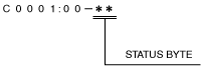
Status byte for DTC
am5ezn00002077
|
Snapshot data
|
Snapshot data item |
Unit |
Data contents |
Data read/use method |
Corresponding data monitor items |
|---|---|---|---|---|
|
ABS
|
Inactive/
Active
|
Antilock braking system
|
—
|
—
|
|
BRK_F_P_R
|
Pa, psi
|
Brake fluid line hydraulic pressure (Raw Value)
|
—
|
BRK_F_P_R
|
|
BTCS
|
Inactive/
Active
|
Brake traction control system
|
—
|
—
|
|
EDC#1
|
Inactive/
Active
|
Engine drag control
|
—
|
—
|
|
LAT_ACCL_R
|
G
|
Lateral acceleration (Raw Value)
|
—
|
LAT_ACCL_R
|
|
LON_ACCL_R
|
G
|
Longitudinal acceleration (Raw Value)
|
—
|
LON_ACCL_R
|
|
STR_ANG_C
|
°
|
Steering wheel angle (Calculated Value)
|
—
|
STR_ANG_C
|
|
TCS
|
Inactive/
Active
|
Traction control system
|
—
|
—
|
|
VPWR
|
V
|
Power supply
|
—
|
VPWR
|
|
VSPD
|
KPH, MPH
|
Vehicle speed
|
—
|
VSPD
|
|
YAW_RATE_R
|
°/S
|
Yaw Rate (Raw Value)
|
—
|
YAW_RATE_R
|
PID/data monitor function
|
PID name (definition) |
Unit/Condition |
Operation condition (reference) |
Action |
|---|---|---|---|
|
BRAKE_SW
|
Off/On
|
• Brake pedal released: Off
• Brake pedal depressed: On
|
Inspect the brake switch.
|
|
BRK_F_P_R
(Raw Value)
|
Pa, psi
|
• Brake pedal depressed: Changes according to the brake fluid pressure
|
Inspect the brake fluid pressure sensor.
|
|
DDS_MODE
|
Not_Learned/Learning/Learned
|
• During initialization: Not_Learned
• During learning: Learning
• Learning completed*: Learned
|
Perform the DTC inspection for the DSC HU/CM.
|
|
DSC_OFF_SW
|
Off/On
|
• DSC OFF switch is released: Off
• DSC OFF switch is depressed: On
|
Inspect the DSC OFF switch.
|
|
DSC_ST
|
Off/On
|
• During DSC OFF mode: Off
• Other than DSC OFF mode: On
|
Perform the DTC inspection for the DSC HU/CM.
|
|
LAT_ACCL_R
(Raw Value)
|
G
|
• Vehicle stopped or driving at constant speed: 0 G
• Cornering to left: Changes 0 G—positive
• Cornering to right: Changes 0 G—negative
|
Perform the DTC inspection for the SAS control module.
|
|
LON_ACCL_C
(Calculated Value)
|
G
|
• Vehicle stopped or driving at constant speed: 0 G
• Vehicle is driving at a acceleration: Changes 0 G—positive
• Vehicle is driving at a deceleration: Changes 0 G—negative
|
Perform the DTC inspection for the SAS control module.
|
|
LON_ACCL_R
(Raw Value)
|
|||
|
PMP_MT_SP
|
Off/On
|
• Pump motor not activated: Off
• Pump motor activated: On
|
Inspect the DSC HU/CM.
|
|
STR_ANG_C
(Calculated Value)
|
°
|
• Steering wheel in neutral position (not turned): 0°
• Steering wheel turned to left: Changes 0°—positive
• Steering wheel turned to right: Changes 0°—negative
|
Perform the DTC inspection for the PCM, DSC HU/CM, and EPS control module.
If a DTC is displayed after performing the DTC inspection for the PCM, DSC HU/CM, and EPS control module, repair the malfunctioning part according to the applicable DTC troubleshooting.
After performing the DTC inspection, perform the following procedures:
• Start the engine and drive the vehicle in a straight line at a speed of 20 km/h or more for several seconds.
If an abnormal value is indicated after verifying the value of the STR_ANG_C again, replace the DSC HU/CM.
|
|
STR_ANG_R
(Raw Value)
|
• Steering wheel position when ignition is switched ON (engine off or on): 0°
• Steering wheel turned to left: Changes 0°—positive
• Steering wheel turned to right: Changes 0°—negative
|
Inspect the following PID.
• STR_ANG
|
|
|
TPMS_TYPE
|
No_DDS/DDS/DDS+TOM_O/DDS+TOM_EU/DDS+TOM_US
|
• TPMS not equipped: No_DDS
• TPMS equipped: DDS
• TPMS equipped (Corresponding to European and U.S. regulations): DDS+TOM_O
• TPMS equipped (Corresponding to European regulations): DDS+TOM_EU
• TPMS equipped (Corresponding to U.S. regulations): DDS+TOM_US
|
Perform the DTC inspection for the DSC HU/CM.
|
|
V_INLET_LF
|
Off/On
|
• Solenoid valve not activated: Off
• Solenoid valve activated: On
|
Inspect the DSC HU/CM.
|
|
V_INLET_LR
|
|||
|
V_INLET_RF
|
|||
|
V_INLET_RR
|
|||
|
V_OUTLET_LF
|
|||
|
V_OUTLET_LR
|
|||
|
V_OUTLET_RF
|
|||
|
V_OUTLET_RR
|
|||
|
V_TRC_LF/RR
|
Off/On
|
• Solenoid valve activated: On
• Solenoid valve not activated: Off
|
Inspect the DSC HU/CM.
|
|
V_TRC_RF/LR
|
|||
|
VPWR_B_SOL
|
V
|
• Ignition switched ON (engine off): Approx. 12.2 V
• Idling: Approx. 14.1 V
|
Inspect power supply circuit.
|
|
VSPD
|
KPH, MPH
|
• Vehicle stopped: 0 KPH, 0 MPH
• Vehicle running: Vehicle speed
|
Inspect the DSC HU/CM.
|
|
WSPD_SEN_LF
|
KPH, MPH
|
• Vehicle stopped: 0 KPH, 0 MPH
• Vehicle running: Vehicle speed
|
Inspect the front ABS wheel-speed sensor.
|
|
WSPD_SEN_LR
|
Inspect the rear ABS wheel-speed sensor.
|
||
|
WSPD_SEN_RF
|
Inspect the front ABS wheel-speed sensor.
|
||
|
WSPD_SEN_RR
|
Inspect the rear ABS wheel-speed sensor.
|
||
|
YAW_RATE_C
(Calculated Value)
|
°/s
|
• Vehicle stopped or driving straight: 0 °/s
• Cornering to left: Changes 0 °/s—positive
• Cornering to right: Changes 0 °/s—negative
|
Perform the DTC inspection for the SAS control module.
|
|
YAW_RATE_R
(Raw Value)
|
Active command modes function
Active command mode table
|
Command name |
Output part |
Operation |
Operating condition |
|---|---|---|---|
|
PMP_MT_SP
|
Pump motor
|
Off/On
|
Switch the ignition to ON
|
|
V_INLET_LF
|
LF inlet solenoid valve
|
||
|
V_INLET_LR
|
LR inlet solenoid valve
|
||
|
V_INLET_RF
|
RF inlet solenoid valve
|
||
|
V_INLET_RR
|
RR inlet solenoid valve
|
||
|
V_OUTLET_LF
|
LF outlet solenoid valve
|
||
|
V_OUTLET_LR
|
LR outlet solenoid valve
|
||
|
V_OUTLET_RF
|
RF outlet solenoid valve
|
||
|
V_OUTLET_RR
|
RR outlet solenoid valve
|
||
|
V_TRC_LF/RR
|
LF/RR linear control solenoid valve
|
Off/On
|
Switch the ignition to ON
|
|
V_TRC_RF/LR
|
RF/LR linear control solenoid valve
|
External tester communication function
|
Diagnostic function name |
Signal received |
Signal sent |
|---|---|---|
|
Malfunction detection function
|
DTC verification signal
|
DTC
|
|
PID/data monitor function
|
Command signal to read selected monitor item
|
Monitored data for requested monitor item
|
|
Active command modes function
|
Operation command signal for selected active command modes item
|
Output part drive signal
|