 |
am6zzw00008893
BRAKE PEDAL REMOVAL/INSTALLATION [L.H.D.]
id041100801250
1. Disconnect the negative battery cable. (See NEGATIVE BATTERY CABLE DISCONNECTION/CONNECTION [SKYACTIV-G 2.0, SKYACTIV-G 2.5].) (See NEGATIVE BATTERY CABLE DISCONNECTION/CONNECTION [SKYACTIV-G 2.0, SKYACTIV-G 2.5 (WITHOUT i-stop)].) (See NEGATIVE BATTERY CABLE DISCONNECTION/CONNECTION [SKYACTIV-D 2.2].)
2. Remove the battery. (See BATTERY REMOVAL/INSTALLATION [SKYACTIV-G 2.0, SKYACTIV-G 2.5].) (See BATTERY REMOVAL/INSTALLATION [SKYACTIV-D 2.2].)
3. Disconnect the brake pipes from the master cylinder. (See MASTER CYLINDER REMOVAL/INSTALLATION [L.H.D.].)
4. For MTX vehicles, disconnect the clutch reserve hose from the master cylinder. (See MASTER CYLINDER REMOVAL/INSTALLATION [L.H.D.].)
5. Remove the side wall (driver side). (See SIDE WALL REMOVAL/INSTALLATION.)
6. Remove the front heat duct (LH). (See FRONT HEAT DUCT REMOVAL/INSTALLATION.)
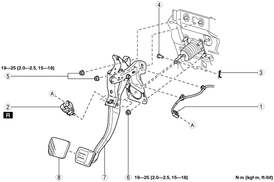
7. Remove in the order indicated in the table.
8. Install in the reverse order of removal.
9. After installation, add brake fluid, bleed the air, and inspect for fluid leakage. (See BRAKE FLUID AIR BLEEDING.)
am6zzw00008893
|
|
1
|
Brake switch connector and wiring harness
|
|
2
|
Brake switch
|
|
3
|
Spring pin
|
|
4
|
Clevis pin
|
|
5
|
Nut
|
|
6
|
Nut
|
|
7
|
Brake pedal
(See Brake Pedal Removal Note.)
|
|
8
|
Pedal pad
|
Brake Pedal Removal Note
1. Move the power brake unit to the vehicle front where the power brake unit fork does not interfere with the brake pedal arm.
2. Remove the brake pedal.
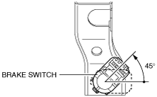
Brake Switch Installation Note
1. Inspect the brake pedal. (See BRAKE PEDAL INSPECTION.)
2. With the brake pedal fully released, insert a new brake switch into the installation hole on the brake pedal.
3. Secure the brake switch by turning it counterclockwise 45°.
ac5wzw00000204
|