 |
am6zzw00008895
POWER BRAKE UNIT REMOVAL/INSTALLATION [L.H.D.]
id041100801850
1. Disconnect the negative battery cable. (See NEGATIVE BATTERY CABLE DISCONNECTION/CONNECTION [SKYACTIV-G 2.0, SKYACTIV-G 2.5].) (See NEGATIVE BATTERY CABLE DISCONNECTION/CONNECTION [SKYACTIV-G 2.0, SKYACTIV-G 2.5 (WITHOUT i-stop)].) (See NEGATIVE BATTERY CABLE DISCONNECTION/CONNECTION [SKYACTIV-D 2.2].)
2. Remove the battery. (See BATTERY REMOVAL/INSTALLATION [SKYACTIV-G 2.0, SKYACTIV-G 2.5].) (See BATTERY REMOVAL/INSTALLATION [SKYACTIV-D 2.2].)
3. Remove the windshield wiper arm and blade. (See WINDSHIELD WIPER ARM AND BLADE REMOVAL/INSTALLATION.)
4. Remove the cowl grille. (See COWL GRILLE REMOVAL/INSTALLATION.)
5. Remove the windshield wiper motor and link. (See WINDSHIELD WIPER MOTOR AND LINK REMOVAL/INSTALLATION.)
6. Remove the cowl panel. (See COWL PANEL REMOVAL/INSTALLATION.)
7. Remove the master cylinder. (See MASTER CYLINDER REMOVAL/INSTALLATION [L.H.D.].)
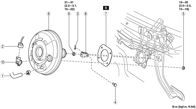
8. Remove in the order indicated in the table.
9. Install in the reverse order of removal.
10. After installation, add brake fluid, bleed the air, and inspect for fluid leakage. (See BRAKE FLUID AIR BLEEDING.)
11. Remove the brake switch. (See BRAKE PEDAL REMOVAL/INSTALLATION [L.H.D.].)
12. Inspect the brake pedal. (See BRAKE PEDAL INSPECTION.)
13. Install a new brake switch. (See BRAKE PEDAL REMOVAL/INSTALLATION [L.H.D.].)
am6zzw00008895
|
|
1
|
Vacuum hose
|
|
2
|
Power brake unit vacuum sensor connector (vehicles with i-stop)
|
|
3
|
Snap pin
|
|
4
|
Clevis pin
|
|
5
|
Nut
|
|
6
|
Power brake unit
|
|
7
|
Gasket
|
|
8
|
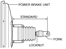
Fork
(See Fork Installation Note.)
|
|
9
|
Locknut
|
|
10
|
Power brake unit vacuum sensor (vehicles with i-stop)
|
Fork Installation Note
1. Install the fork as shown in the figure.
am6zzw00008896
|