am6xun00001048
|
DSC HU/CM
id041500103300
Outline
am6xun00001048
|
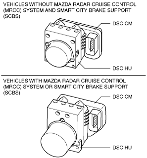
DSC HU Part Purpose/Function
DSC HU Part Construction
Function of main component parts
|
Part name |
Function |
|---|---|
|
Inlet solenoid valve
|
• Adjusts the fluid pressure in each brake system according to DSC HU/CM signals.
|
|
Outlet solenoid valve
|
• Adjusts the fluid pressure in each brake system according to DSC HU/CM signals.
|
|
Linear control solenoid valve
|
• Switches the brake hydraulic circuits during and according to normal braking, ABS and EBD control, TCS control and DSC control.
|
|
Reservoir
|
• Closes the hydraulic circuit between the master cylinder and reservoir if the brake pedal is depressed.
• Temporarily stores brake fluid from the caliper piston when pressure reduces during ABS control and EBD control.
• Opens the hydraulic circuit between the master cylinder and reservoir when pressure increases during TCS control and DSC control.
|
|
Pump
|
• Returns the brake fluid stored in the reservoir to the master cylinder during ABS control and DSC control.
• Increases brake fluid pressure and sends brake fluid to each caliper piston during TCS control and DSC control.
|
|
Pump motor
|
• Operates the pump according to DSC HU/CM signals.
|
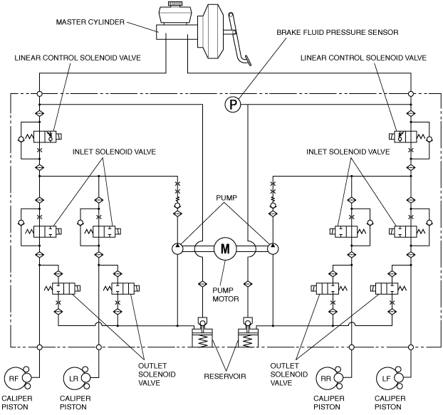
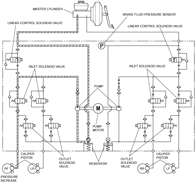
Hydraulic circuit diagram
am6zzn00001805
|
Operation
During normal braking
Solenoid valve operation table
|
Linear control solenoid valve |
Inlet solenoid valve |
Outlet solenoid valve |
Pump motor, pump |
|||||||
|---|---|---|---|---|---|---|---|---|---|---|
|
LF—RR |
RF—LR |
LF |
RF |
LR |
RR |
LF |
RF |
LR |
RR |
|
|
OFF (open)
|
OFF (open)
|
OFF (closed)
|
Stopped
|
|||||||
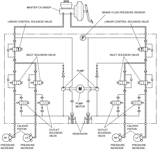
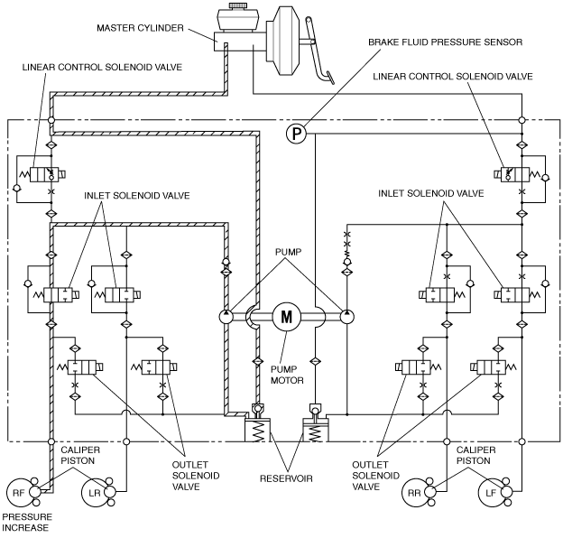
Hydraulic circuit diagram
am6zzn00001806
|
During ABS and EBD control
Solenoid valve operation table
|
|
Linear control solenoid valve |
Inlet solenoid valve |
Outlet solenoid valve |
Pump motor, pump |
|||||||
|---|---|---|---|---|---|---|---|---|---|---|---|
|
LF—RR |
RF—LR |
LF |
RF |
LR |
RR |
LF |
RF |
LR |
RR |
||
|
During pressure increase mode
|
OFF (open)
|
OFF (open)
|
OFF (closed)
|
Stopped
|
|||||||
|
During pressure maintain mode
|
OFF (open)
|
ON (closed)
|
OFF (closed)
|
Stopped
|
|||||||
|
During pressure reduction mode
|
OFF (open)
|
ON (closed)
|
ON (open)
|
Operating
|
|||||||
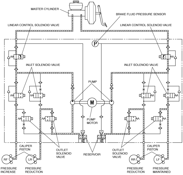
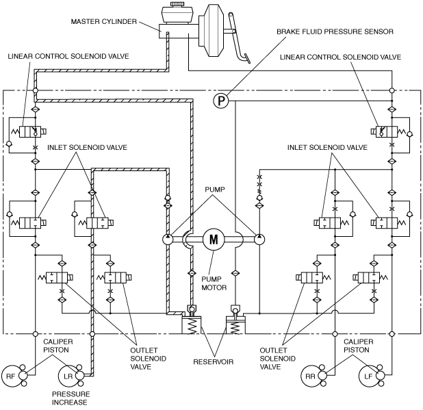
Hydraulic circuit diagram
am6zzn00001807
|
During TCS control
Solenoid valve operation table
|
|
Linear control solenoid valve |
Inlet solenoid valve |
Outlet solenoid valve |
Pump motor, pump |
|||||||
|---|---|---|---|---|---|---|---|---|---|---|---|
|
LF—RR |
RF—LR |
LF |
RF |
LR |
RR |
LF |
RF |
LR |
RR |
||
|
During pressure increase mode
|
OFF (open)
|
ON (adjusting pressure)
|
ON (closed)
|
OFF (open)
|
ON (closed)
|
OFF (closed)
|
Operating
|
||||
|
During pressure maintain mode
|
OFF (open)
|
ON (adjusting pressure)
|
ON (closed)
|
OFF (open)
|
ON (closed)
|
OFF (closed)
|
Operating
|
||||
|
During pressure reduction mode
|
OFF (open)
|
ON (adjusting pressure)
|
ON (closed)
|
OFF (open)
|
ON (closed)
|
OFF (closed)
|
Operating
|
||||
Hydraulic circuit diagram
am6zzn00001808
|
During DSC control (to suppress oversteer tendency)
Solenoid valve operation table
|
|
Linear control solenoid valve |
Inlet solenoid valve |
Outlet solenoid valve |
Pump motor, pump |
|||||||
|---|---|---|---|---|---|---|---|---|---|---|---|
|
LF—RR |
RF—LR |
LF |
RF |
LR |
RR |
LF |
RF |
LR |
RR |
||
|
During pressure increase mode
|
OFF (open)
|
ON (closed)
|
OFF (open)
|
OFF (open)
|
ON (closed)
|
OFF (open)
|
OFF (closed)
|
OFF (closed)
|
ON (open)
|
OFF (closed)
|
Operating
|
|
During pressure maintain mode
|
OFF (open)
|
ON (closed)
|
OFF (open)
|
ON (closed)
|
ON (closed)
|
OFF (open)
|
OFF (closed)
|
OFF (closed)
|
ON (open)
|
OFF (closed)
|
Operating
|
|
During pressure reduction mode
|
OFF (open)
|
ON (closed)
|
OFF (open)
|
ON (closed)
|
ON (closed)
|
OFF (open)
|
OFF (closed)
|
ON (open)
|
ON (open)
|
OFF (closed)
|
Operating
|
Hydraulic circuit diagram
am6zzn00001809
|
During DSC control (to suppress understeer tendency)
Solenoid valve operation table
|
|
Linear control solenoid valve |
Inlet solenoid valve |
Outlet solenoid valve |
Pump motor, pump |
|||||||
|---|---|---|---|---|---|---|---|---|---|---|---|
|
LF—RR |
RF—LR |
LF |
RF |
LR |
RR |
LF |
RF |
LR |
RR |
||
|
During pressure increase mode
|
OFF (open)
|
ON (closed)
|
OFF (open)
|
ON (closed)
|
OFF (open)
|
OFF (open)
|
OFF (closed)
|
ON (open)
|
OFF (closed)
|
OFF (closed)
|
Operating
|
|
During pressure maintain mode
|
OFF (open)
|
ON (closed)
|
OFF (open)
|
ON (closed)
|
ON (closed)
|
OFF (open)
|
OFF (closed)
|
ON (open)
|
OFF (closed)
|
OFF (closed)
|
Operating
|
|
During pressure reduction mode
|
OFF (open)
|
ON (closed)
|
OFF (open)
|
ON (closed)
|
ON (closed)
|
OFF (open)
|
OFF (closed)
|
ON (open)
|
ON (open)
|
OFF (closed)
|
Operating
|
Hydraulic circuit diagram
am6zzn00001810
|
DSC CM Part Function
Function table
|
Function name |
Contents |
|---|---|
|
ABS control function
|
• Controls brake fluid pressure when braking to maintain directional stability, ensure steerability, and reduce stopping distance.
|
|
EBD control function
|
• Constantly controls proper distribution of brake fluid pressure to the front and rear wheels according to vehicle load, road surface, and vehicle speed conditions to prevent early lock-up of the rear wheels.
|
|
TCS control function
|
• Controls traction to within the road surface friction limit and according to road and driving conditions to improve starting and acceleration performance, and safety.
|
|
DSC control function
|
• Suppresses strong over-steer and under-steer tendencies when turning by controlling engine output and braking of each wheel to assure driving safety.
|
|
Brake assist control function
|
• The brake pedal depression speed and force is calculated from the brake fluid pressure sensor signal. If it exceeds the specification, an emergency braking situation is determined and a higher amount of hydraulic pressure than the normal specified amount is generated in the hydraulic unit and supplied to each wheel based on the activation of each solenoid valve, pump motor, and pump.
• If a condition is detected in which emergency braking is anticipated by the change in speed of the accelerator pedal position, the gap between the brake pad and disc plate is reduced to enhance the response when braking.
|
|
Vehicle roll prevention function (ATX)
|
• For detailed information on the vehicle roll prevention function, refer to VEHICLE ROLL PREVENTION FUNCTION. (See VEHICLE ROLL PREVENTION FUNCTION.)
|
|
Hill Launch Assist (HLA) control function
|
• For detailed information on the Hill Launch Assist (HLA), refer to HILL LAUNCH ASSIST (HLA). (See HILL LAUNCH ASSIST (HLA).)
|
|
Tire Pressure Monitoring System (TPMS) control function
|
• For detailed information on the TPMS, refer to TIRE PRESSURE MONITORING SYSTEM (TPMS). (See TIRE PRESSURE MONITORING SYSTEM (TPMS).)
|
|
Vehicle roll prevention function (ATX)
|
• For detailed information on the vehicle roll prevention function, refer to VEHICLE ROLL PREVENTION FUNCTION. (See VEHICLE ROLL PREVENTION FUNCTION.)
|
|
Secondary collision reduction (SCR) control function
|
• For detailed information on the secondary collision reduction (SCR), refer to SECONDARY COLLISION REDUCTION (SCR). (See SECONDARY COLLISION REDUCTION (SCR).)
|
|
CAN communication function
|
• Outputs the vehicle speed signal and DSC system warning control data via CAN lines.
|
|
On-board diagnostic system
|
• A function that allows important parts of the DSC control system to perform self-diagnosis. In case a malfunction occurs, the warning lights illuminate to alert the driver, and at the same time a DTC is stored in the DSC HU/CM.
• When a malfunction is determined as a result of the on-board diagnostic test, system control is suspended or limited to prevent any dangerous situation while driving.
|
|
Automatic configuration function
|
• When the ignition is switched ON or the engine is started after the DSC HU/CM have been replaced, the DSC CM reads data from the instrument cluster via CAN communication to perform automatic configuration.
|
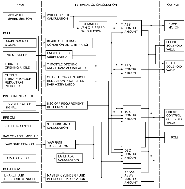
Block diagram
am6xun00001049
|