ELECTRIC POWER STEERING (EPS) CONTROL MODULE
id061300245500
Purpose/ Function
• The EPS Control Module (CM) calculates the optimum assist current based on the steering torque signal from the torque sensor installed to the steering column and the vehicle speed signal sent via CAN transmission from the PCM.
• The following steering angle signals are output via CAN communication.
-
― Steering angle (relative angle) signal
-
• Set the steering position to 0 degrees when the ignition is switched ON (engine off or on) to output the steering angle when steering from that position.
― Steering angle (estimated absolute angle) signal
-
• The EPS CM outputs the calculated steering angle value to the CAN as a steering angle (estimated absolute angle) signal for other systems requiring steering angle information.
• The EPS CM performs the steering wheel angle neutral position determination using the steering wheel angle neutral position automatic learning function based on the wheel speed signal, lateral-G signal, and yaw rate signal while driving.
• Set the angle to 0 degrees during the steering wheel angle neutral position determination and the EPS CM calculates the steering angle, and outputs it.
-
Note
-
• The steering angle sensor signal is not used for the steering angle (estimated absolute angle) signal calculation.
• Before the steering wheel angle neutral position auto learning is completed, the EPS CM receives a steering angle (absolute angle) signal from the steering angle sensor via the start stop unit and outputs the signal to the other modules through the CAN communication (with adaptive front lighting system (AFS), and/or Smart City Brake Support (SCBS)).
• After the steering angle neutral position auto learning is completed, the EPS CM outputs an EPS status signal, which is calculated by EPS CM itself, through the CAN communication.
• The steering wheel angle neutral position is cleared when 1 min or more has elapsed after the ignition is switched off.
• The EPS CM controls the following functions:
Function Table
|
Control item
|
Function
|
|
EPS motor current control
|
• Normal control
-
― Calculates the proper assist current based on the steering torque, and the vehicle and engine speeds, and outputs a target current to the EPS motor.
• System overheating protection control
-
― Monitors the temperature of the motherboard in the EPS CM and controls the motor current gradually to prevent overheating of the system.
• EPS motor backup control
-
― Even if a phase 1 open circuit malfunction in the EPS motor occurs, output current to the EPS motor is controlled so that steering assist is maintained.
• Torque sensor backup control (With Lane-Keep Assist System)
-
― Even if an error occurs in the torque sensor signal, the torque sensor backup control performs control to maintain steering assist to the extent possible.
• Resolver sensor backup control (With Lane-Keep Assist System)
-
― Even if an open circuit malfunction occurs in the resolver sensor, the resolver sensor backup control performs control to maintain steering assist to the extent possible.
― Monitors the temperature of the motherboard in the EPS CM and controls the motor current in steps to prevent overheating of the system.
• EPS i-stop control
-
― Control current to the EPS motor is increased or decreased according to the operation status of the i-stop system.
|
|
On-board diagnostic function
|
• The main part of the system control includes the self-diagnosis function. In case a malfunction occurs, the power steering malfunction indicator light/master warning light illuminates to alert the driver, and a DTC is stored in the EPS CM at the same time.
• As a result of the on-board diagnosis, when a malfunction is determined, system control is suspended or limited to assure safety while driving.
|
|
CAN communication function
|
• Outputs the EPS status signal and the power steering malfunction indicator light illuminates on request via CAN lines.
• Outputs the steering angle (absolute angle) signal, steering angle (relative angle) signal and steering angle (estimated absolute angle) signal
|
|
Automatic configuration function
|
• When the ignition is switched to ON or the engine is started after the EPS CM have been replaced, the EPS CM reads data from the instrument cluster via CAN communication to perform automatic configuration.
|
|
Steering wheel angle neutral position automatic learning function
|
• When the ignition is switched from OFF to ON (engine on) and the vehicle is driven normally, the steering wheel angle neutral position is learned automatically based on the wheel speed signal, lateral-G signal, and yaw rate signal.
|
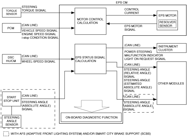
Block Diagram
Construction
• The EPS CM is installed to the steering column and integrated with the EPS motor.
• For vehicles equipped with a system requiring steering angle information directly after the vehicle starts to be driven, a steering angle sensor is equipped.
Operation
• The EPS CM calculates the required assist torque based on the steering torque signal from the torque sensor. When the vehicle starts to be driven, the required assist torque is calculated based on the vehicle speed signal sent from the PCM via CAN in addition to the steering torque signal.
• When the required assist torque is determined, the EPS CM outputs the control current to the EPS motor and the EPS motor generates the assist torque.
• The EPS system control uses the steering angle (estimated absolute angle) signal.
Ignition is switched ON (engine off or on)
-
• For vehicle equipped with a system requiring steering angle information directly after the vehicle starts to be driven, a steering angle sensor is equipped.
• For vehicles with a steering angle sensor, the EPS CM receives the steering angle sensor signal via the start stop unit. The EPS CM outputs the steering angle value as a steering angle (absolute angle) signal.
• The following systems perform control using a steering angle (absolute angle) signal until the EPS CM completes steering wheel angle neutral position determination after the vehicle starts to be driven.
-
― AFS (Adaptive Front lighting System)
― Smart City Brake Support (SCBS)
-
Note
-
• Because the accuracy of the steering angle (absolute angle) signal is lower than the steering angle (estimated absolute angle) signal, if the EPS CM completes steering wheel angle neutral position determination, each system requiring steering angle information performs control using a steering angle (estimated absolute angle) signal instead of a steering angle (absolute angle) signal.
• The EPS CM regards the steering position when the ignition is switched ON (engine off or on) as 0 degrees, and outputs the steering angle value steered from that position as a steering angle (relative angle) signal.
Vehicle driving
-
• When the vehicle starts to be driven, the EPS CM performs steering wheel angle neutral position determination based on the following signals:
-
― Wheel speed signal: Determines straight-driving if there is no rotation speed difference between the left/right wheels.
― Lateral-G signal: Determines straight-driving if lateral-G is not produced.
― Yaw rate signal: Determines straight-driving if yaw momentum is not produced.
• If the EPS CM completes steering wheel angle neutral position determination, the steering angle neutral position is set. The EPS CM regards the steering wheel angle neutral position as 0 degrees, calculates the estimated absolute steering angle, and outputs the steering angle (estimated absolute angle) signal to CAN.
Ignition is switched off
-
• The steering wheel angle neutral position is cleared when 1 min or more has elapsed after the ignition is switched off.
EPS Motor Current Control
-
Normal control
-
• The optimum assist current is calculated based on the steering force signal from the torque sensor and the vehicle and the engine speed signal from the PCM, and then the control current is output to the EPS motor.
-
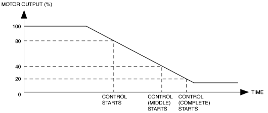
System overheating protection control
-
• The system overheating protection control lowers the current output to the EPS motor if the steering mechanism is turned from lock to lock continuously or the steering rack turning limit is reached repeatedly.
-
Note
-
• During system overheating protection control, the assist force will feel weaker due to a decrease in the control current. This is normal for the EPS CM to prevent the EPS motor from burning or seizure, and it does not indicate a malfunction.
• While the assist force weakens during this period of time, steering operation can be performed.
• The system overheating protection control has middle and complete steps, and it can verify current conditions and the history using the PID/data monitor function and snap shot data.
-
― System overheating protection control (middle): Motor output is 40 % or less (reference)
― System overheating protection control (complete): Motor output is 20 % or less (reference)
• The current output returns to normal if the temperature in the system decreases to the normal operation temperature.
-
EPS motor backup control
-
• Even if an open circuit malfunction occurs in 1 out of the 3 phases in the EPS motor line, the EPS motor backup control performs control to maintain steering assist.
• If the EPS CM detects a phase 1 open circuit malfunction in the EPS motor, the EPS CM controls output current to the EPS motor using a calculation method different than during normal EPS CM control. As a result, even with a phase 1 open circuit malfunction, the steering assist can be maintained.
-
Note
-
• If a phase 1 open circuit malfunction is detected in the EPS motor, the EPS CM stores DTC U2011:72 and illuminates the electric power steering malfunction indicator light.
• If the steering wheel is operated during EPS motor backup control, the steering wheel operation may feel heavier (resistance).
-
Torque sensor backup control (With Lane-Keep Assist System)
-
• Even if an error is detected in the torque sensor signal, the torque sensor backup control performs control to maintain steering assist.
• If the EPS CM detects a torque sensor signal error, the EPS CM controls output current to the EPS motor using a calculation method different from that during normal EPS CM control, and maintains steering assist.
• A steering wheel vibrates when steering wheel is operated during torque sensor backup control.
-
Note
-
• When the torque sensor backup control is performed, the EPS CM stores DTC C200B:1C or DTC C200C:1C and turns the power steering malfunction indicator light on.
• If the steering wheel is operated during torque sensor backup control, normal assist force may not be generated.
-
Resolver sensor backup control (With Lane-Keep Assist System)
-
• Even if an open circuit malfunction occurs in the resolver sensor, the resolver sensor backup control performs control to maintain steering assist.
• If the EPS CM detects an open circuit malfunction in the resolver sensor, the EPS CM controls output current to the EPS motor using a calculation method different from that during normal EPS CM control. As a result, even with an open circuit in the resolver sensor, the steering assist can be maintained.
• A steering wheel vibrates when steering wheel is operated during resolver sensor backup control.
• The EPS CM flashes the power steering malfunction indicator light and the EPS warning alarm sounds intermittently to alert the driver.
-
Note
-
• If an open circuit malfunction is detected in the resolver sensor, the EPS CM stores DTC C200D:1C.
• The EPS CM cannot calculate the optimum output current to the EPS motor during the resolver sensor backup control. Therefore, the temperature in the EPS system may increase only by operating the normal steering wheel repeatedly.
• If the temperature in the EPS system increases, the EPS CM controls the output current to the EPS motor and lowers output to the EPS motor to prevent the EPS motor from burning or seizure. Although the assist force weakens when output to the EPS motor is lowered, steering operation can be performed.
-
― If output to the EPS motor decreases below the specified value, the flashing interval for the power steering malfunction indicator light and the EPS warning alarm sound interval are shortened to warn the driver.
― If output to the EPS motor decreases further, the power steering malfunction indicator light switches from flashing to illumination and the EPS warning alarm sounds continuously.
― If EPS system overheating continues, the EPS CM stops the output current to the EPS motor and cancels assistance. At this time, the power steering malfunction indicator light remains illuminated, however, the warning beep sound stops.
-
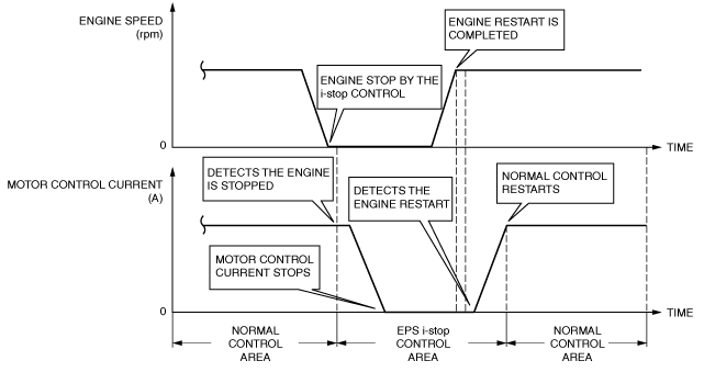
EPS i-stop control
-
• If it is detected that the engine is stopped by the i-stop control based on the i-stop condition signal from the PCM, the EPS motor control current is stopped.
• If it is detected that the engine is restarted by the i-stop control, the EPS motor control current is increased and the system returns to normal control.
• If the steering wheel is operated during EPS i-stop control, assist is performed (normal control) according to that steering.
• If a malfunction is detected in the i-stop condition signal from the PCM, EPS i-stop control is not operated, and normal control is performed.
• Depending on the vehicle condition, the EPS CM may continue assistance even after the engine is stopped.
Fail-safe
|
DTC No.
|
Fail-safe function
|
|
U2300:54
|
• Control enabled
• Power steering malfunction indicator light: Not illuminates
|
|
U2300:55
|
• Control enabled
• Power steering malfunction indicator light: Illuminates
|
|
U2300:56
|
• Control enabled
• Power steering malfunction indicator light: Not illuminates
|
|
U3000:16
|
• Control disabled
• Power steering malfunction indicator light: Illuminates
|
|
U3000:1C
|
|
U3000:28
|
|
U3000:41
|
|
U3000:46
|
• Control is maintained in fail mode
• Power steering malfunction indicator light: Not illuminates
|
|
U3000:47
|
• Control disabled
• Power steering malfunction indicator light: Illuminates
|
|
U3000:49
|
|
U3000:4B
|
• Control is maintained in fail mode
• Power steering malfunction indicator light: Not illuminates
|
|
U3000:61
|
• Control disabled
• Power steering malfunction indicator light: Illuminates
|
|
U3000:73
|
|
U3000:96
|
|
U3003:16
|
• Control is maintained by gradually decreasing the motor control current
-
― However, control is inhibited if the power supply voltage is the specified value of less
• Power steering malfunction indicator light: Illuminates
|
|
U3003:17
|
• Control disabled
• Power steering malfunction indicator light: Illuminates
|