 |
am6zzw00010639
REFRIGERANT LINE REMOVAL/INSTALLATION
id071100803000
L.H.D.
SKYACTIV-G 2.0, SKYACTIV-G 2.5
1. Disconnect the negative battery cable. (See NEGATIVE BATTERY CABLE DISCONNECTION/CONNECTION [SKYACTIV-G 2.0, SKYACTIV-G 2.5].)(See NEGATIVE BATTERY CABLE DISCONNECTION/CONNECTION [SKYACTIV-G 2.0, SKYACTIV-G 2.5 (WITHOUT i-stop)].)
2. Discharge the refrigerant. (See REFRIGERANT RECOVERY.)(See REFRIGERANT CHARGING.)
3. Remove the plug hole plate. (See PLUG HOLE PLATE REMOVAL/INSTALLATION [SKYACTIV-G 2.0, SKYACTIV-G 2.5].)
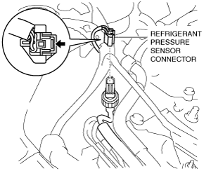
4. Disconnect the refrigerant pressure sensor connector.
am6zzw00010639
|
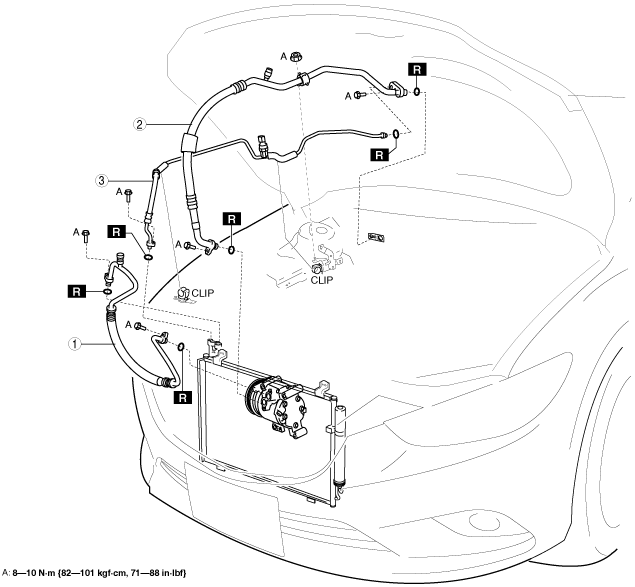
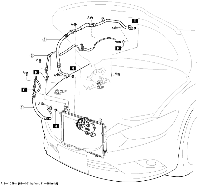
5. Remove in the order indicated in the table. Do not allow compressor oil to spill.
am6zzw00012957
|
|
1
|
Cooler hose (HI)
|
|
2
|
Cooler hose (LO)
|
|
3
|
Cooler pipe
|
6. Install in the reverse order of removal.
7. Perform the refrigerant system performance test. (See REFRIGERANT SYSTEM PERFORMANCE TEST.)
SKYACTIV-D 2.2
1. Disconnect the negative battery cable. (See NEGATIVE BATTERY CABLE DISCONNECTION/CONNECTION [SKYACTIV-D 2.2].)
2. Discharge the refrigerant. (See REFRIGERANT RECOVERY.)(See REFRIGERANT CHARGING.)
3. Remove the engine cover. (See ENGINE COVER REMOVAL/INSTALLATION [SKYACTIV-D 2.2].)
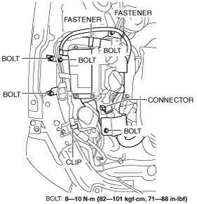
4. Disconnect the connector.
am6zzw00010641
|
5. Detach the fastener.
6. Remove the bolts.
7. Remove the clip.
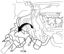
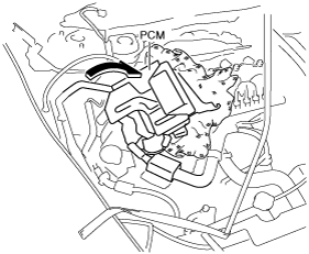
8. Set the PCM out of the way.
am6zzw00011156
|
9. Disconnect the refrigerant pressure sensor connector.
am6zzw00010642
|
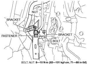
10. Detach the fastener.
am6zzw00010643
|
11. Remove the nut.
12. Remove the bolt.
13. Remove the bracket.
14. Set the PCM out of the way.
am6zzw00010644
|
15. Remove in the order indicated in the table. Do not allow compressor oil to spill.
am6zzw00012958
|
|
1
|
Cooler hose (HI)
|
|
2
|
Cooler hose (LO)
|
|
3
|
Cooler pipe
|
16. Install in the reverse order of removal.
17. Perform the refrigerant system performance test. (See REFRIGERANT SYSTEM PERFORMANCE TEST.)
R.H.D.
SKYACTIV-G 2.0, SKYACTIV-G 2.5
1. Disconnect the negative battery cable. (See NEGATIVE BATTERY CABLE DISCONNECTION/CONNECTION [SKYACTIV-G 2.0, SKYACTIV-G 2.5].)(See NEGATIVE BATTERY CABLE DISCONNECTION/CONNECTION [SKYACTIV-G 2.0, SKYACTIV-G 2.5 (WITHOUT i-stop)].)
2. Discharge the refrigerant. (See REFRIGERANT RECOVERY.)(See REFRIGERANT CHARGING.)
3. Remove the plug hole plate. (See PLUG HOLE PLATE REMOVAL/INSTALLATION [SKYACTIV-G 2.0, SKYACTIV-G 2.5].)
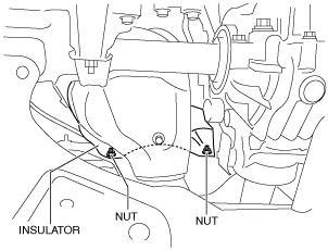
4. Remove the nut.
ac5wzw00001827
|
5. Remove the insulator.
6. Disconnect the refrigerant pressure sensor connector.
am6zzw00010639
|
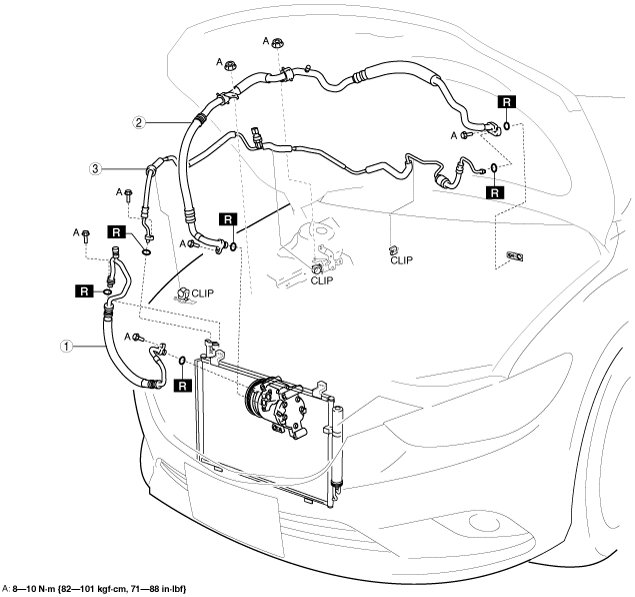
7. Remove in the order indicated in the table. Do not allow compressor oil to spill.
am6zzw00012959
|
|
1
|
Cooler hose (HI)
|
|
2
|
Cooler hose (LO)
|
|
3
|
Cooler pipe
|
8. Install in the reverse order of removal.
9. Perform the refrigerant system performance test. (See REFRIGERANT SYSTEM PERFORMANCE TEST.)
SKYACTIV-D 2.2
1. Disconnect the negative battery cable. (See NEGATIVE BATTERY CABLE DISCONNECTION/CONNECTION [SKYACTIV-D 2.2].)
2. Discharge the refrigerant. (See REFRIGERANT RECOVERY.)(See REFRIGERANT CHARGING.)
3. Remove the engine cover. (See ENGINE COVER REMOVAL/INSTALLATION [SKYACTIV-D 2.2].)
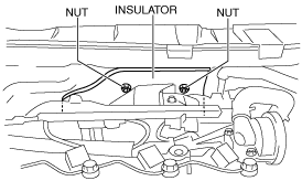
4. Remove the nut from underside of vehicle.
ac5wzw00001830
|
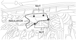
5. Remove the nut from top side of vehicle.
am6zzw00011157
|
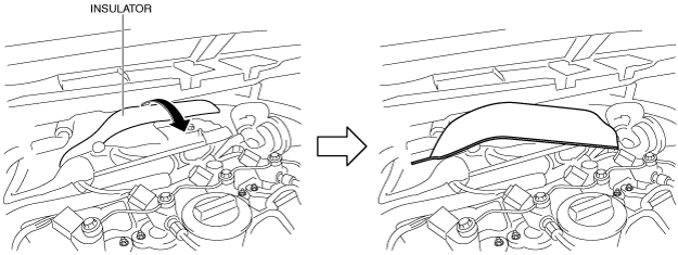
6. Remove the insulator as shown in the figure.
am6zzw00011158
|
7. Disconnect the connector.
am6zzw00010641
|
8. Detach the fastener.
9. Remove the bolts.
10. Remove the clip.
11. Set the PCM out of the way.
am6zzw00011156
|
12. Disconnect the refrigerant pressure sensor connector.
am6zzw00010642
|
13. Detach the fastener.
am6zzw00010643
|
14. Remove the nut.
15. Remove the bolt.
16. Remove the bracket.
17. Set the PCM out of the way.
am6zzw00010644
|
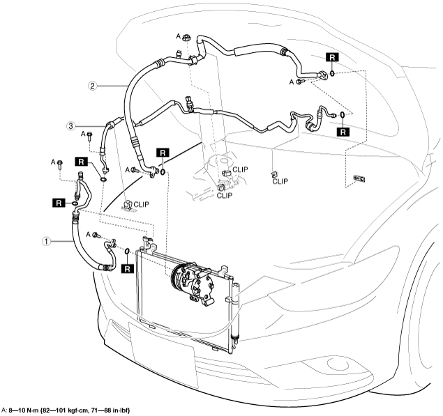
18. Remove in the order indicated in the table. Do not allow compressor oil to spill.
am6zzw00012960
|
|
1
|
Cooler hose (HI)
|
|
2
|
Cooler hose (LO)
|
|
3
|
Cooler pipe
|
19. Install in the reverse order of removal.
20. Perform the refrigerant system performance test. (See REFRIGERANT SYSTEM PERFORMANCE TEST.)
Refrigerant Line Installation Note (1)
1. Apply compressor oil to the O-rings and connect the joints.
2. Tighten the joints.
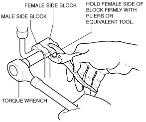
Block joint type
1. Tighten the joint bolt by hand.
2. Connect the block joint type pipes by grasping the female side of the block with pliers or similar tool and holding firmly, then tighten the connection bolt or nut with a torque wrench.
am6zzw00010648
|
Refrigerant Line Installation Note (2)
1. After replacing the refrigerant line, add compressor oil to the refrigeration cycle.