am6zzn00004303
|
FULL-AUTO AIR CONDITIONER SYSTEM [FULL-AUTO AIR CONDITIONER]
id0740a1004000
Outline
Function
am6zzn00004303
|
Airflow temperature control
Airflow volume control
Airflow mode control
Air intake control
A/C compressor control
Air conditioner i-stop control (With i-stop)
am6zzn00004304
|
Construction
Block diagram
am6zzn00004305
|
System wiring diagram
am6zzn00004306
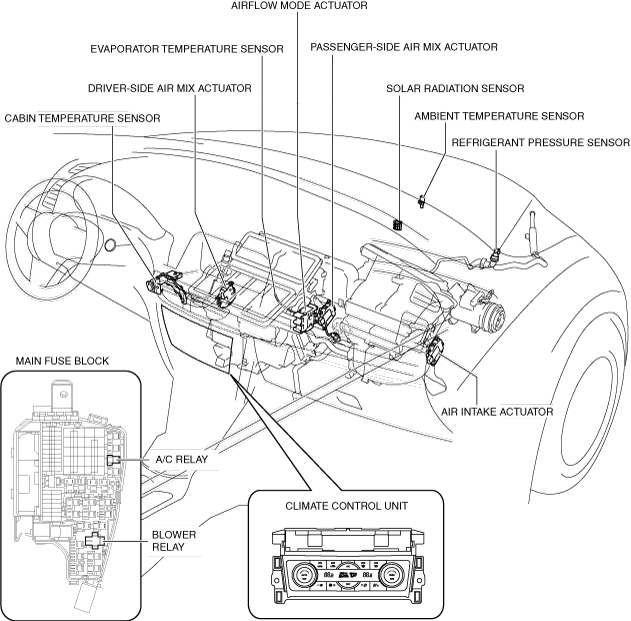
|
Structural view
am6zzn00004307
|
am6zzn00004308
|
Operation
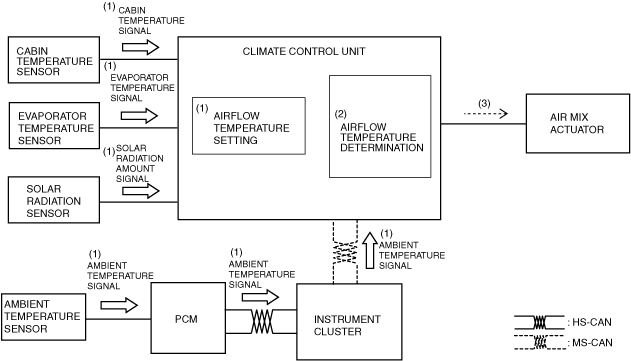
Airflow temperature control
1. The climate control unit performs airflow temperature determination (2) based on the signals (1) from each sensor which change according to the airflow temperature setting and the vehicle conditions.
2. The climate control unit drives (3) the air mix actuator based on the results of the airflow temperature determination and corrections.
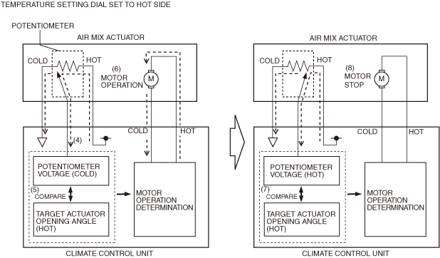
am6zzn00005052
|
3. The climate control unit detects the current air mix actuator opening angle based on the potentiometer voltage (4).
4. The climate control unit compares (5) the target actuator opening angle with the voltage from the potentiometer.
5. When the potentiometer voltage value differs from the target actuator opening angle, the climate control unit drives (6) the air mix actuator motor.
6. When the potentiometer voltage value matches (7) the target actuator opening angle, the climate control unit stops (8) the air mix actuator motor.
am6zzn00004310
|
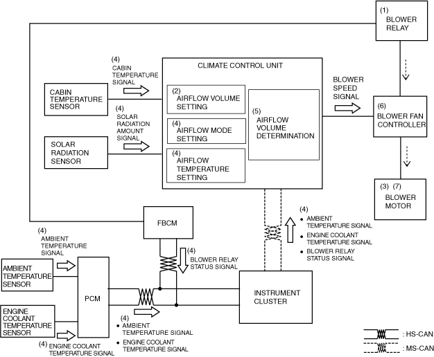
Airflow volume control
1. When the ignition is switched ON (engine off or on), the front body control module (FBCM) turns the blower relay on (1).
2. When the airflow volume setting on the climate control unit is turned on (2), the blower motor (3) rotates.
3. The climate control unit performs airflow volume determination (5) based on the airflow volume setting and the signals from each sensor (4).
4. Based on the result of the airflow volume determination and correction, the climate control unit control the blower fan controller (6) and changes the airflow volume (blower motor applied voltage).
5. The rotation speed of the blower motor (7) changes according to the applied voltage from the blower fan controller.
am6zzn00004311
|
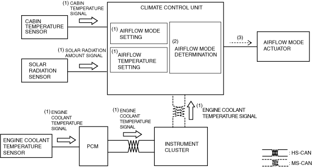
Airflow mode control
1. The climate control unit performs airflow mode determination (2) based on the signals (1) from each sensor which change according to the airflow mode setting and the vehicle conditions.
2. The climate control unit drives the airflow mode actuator (3) according to the results of the airflow mode determination and corrections.
am6zzn00005053
|
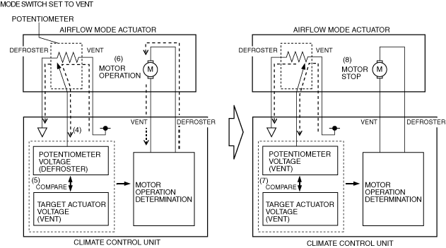
3. The climate control unit detects the current airflow mode actuator opening angle based on the potentiometer voltage (4).
4. The climate control unit compares (5) the target actuator voltage value with the voltage from the potentiometer.
5. When the potentiometer voltage value differs from the target actuator voltage value, the climate control unit drives (6) the airflow mode actuator motor.
6. When the potentiometer voltage value matches (7) the target actuator voltage value, the climate control unit stops (8) the airflow mode actuator motor.
am6zzn00004313
|
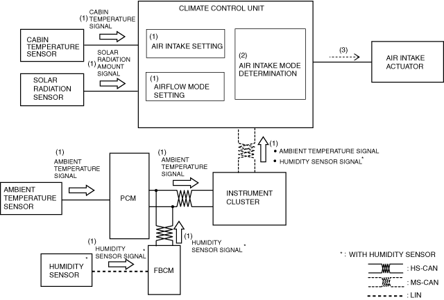
Air intake control (potentiometer type air intake actuator)
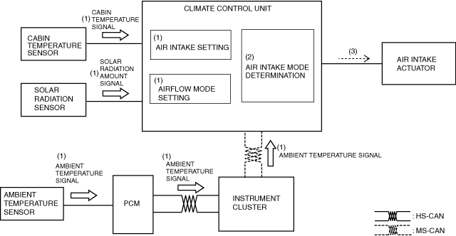
1. The climate control unit performs air intake mode determination (2) based on the signals (1) from the air intake setting and the vehicle conditions.
2. The climate control unit drives the air intake actuator (3) according to the result of the air intake mode determination and corrections.
am6zzn00004314
|
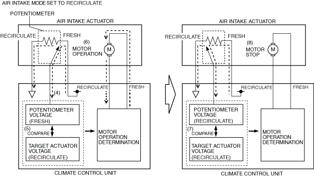
3. The climate control unit detects the current air intake actuator opening angle based on the potentiometer voltage (4).
4. The climate control unit compares (5) the target actuator voltage value with the voltage from the potentiometer.
5. When the potentiometer voltage value differs from the target actuator voltage value, the climate control unit drives (6) the air intake actuator motor.
6. When the potentiometer voltage value matches (7) the target actuator voltage value, the climate control unit stops (8) the air intake actuator motor.
am6zzn00004315
|
Air intake control (mechanical lock type air intake actuator)
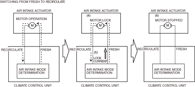
1. The climate control unit performs air intake mode determination (2) based on the signals (1) from the air intake setting and the vehicle conditions.
2. The climate control unit drives the air intake actuator (3) according to the result of the air intake mode determination and corrections.
am6zzn00005054
|
3. When the air intake actuator moves to FRESH or REC, the motor locks (4).
4. When the motor locks and is under excessive load, the current value flowing from the climate control unit increases more than the specification (lock current).
5. When the lock current (5) is detected, the climate control unit stops the motor drive signal (6) to the air intake actuator.
am6zzn00004317
|
A/C compressor control
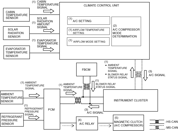
1. The climate control unit performs A/C compressor mode determination (2) based on the signals (1) from each sensor which change according to the A/C setting and the vehicle conditions.
2. The climate control unit sends (3) the A/C signal to the PCM according to the result of the A/C compressor mode determination and corrections.
3. The PCM turns the A/C relay on (4) based on the signals from each sensor which change according to the A/C signal and the vehicle conditions.
4. When the A/C relay turns on, the magnetic clutch turns on (5).
am6zzn00005055
|
Air conditioner i-stop control (With i-stop)
i-stop (engine stop control) inhibit conditions
|
No. |
Item |
Vehicle condition |
|---|---|---|
|
1
|
Climate control unit malfunction determined
|
A DTC is detected in relation to the following parts:
• Solar radiation sensor
• Ambient temperature sensor
• Cabin temperature sensor
• Evaporator temperature sensor
• Engine coolant temperature sensor
• Airflow mode actuator
• Air mix actuator
|
|
2
|
CAN line error determined
|
Signal reception error occurs on climate control unit side in relation to the following signals:
• Ambient temperature signal
• Engine coolant temperature signal
• Engine operation status signal (i-stop status signal)
|
|
3
|
Ambient temperature
|
Ambient temperature is -10 °C {14 °F} or below, or 50 °C {122 °F} or more
|
|
4
|
Airflow mode control status
|
During manual defroster control
|
|
5
|
Set temperature, compressor control mode
|
MAX HOT or MAX COLD (A/C or ECO mode)
|
|
6
|
Auto air conditioner target temperature attainment status
|
If any of the following signals do not meet the i-stop (engine stop control) permit conditions (Comfortable cabin temperature control not performed):
• Cabin temperature (cabin target temperature and cabin temperature relation)
• Evaporator temperature
• Heater core temperature
|
i-stop (engine stop control) permit conditions
|
No. |
Item |
Vehicle condition |
|---|---|---|
|
1
|
Blower motor control status
|
• Blower motor is off
• However, i-stop (engine stop control) inhibit conditions No.1 to 3 must not be in effect.
|
|
2
|
Set temperature, compressor control mode
|
• MAX COLD
• Compressor control: Off
• Blower motor is ON
• However, i-stop (engine stop control) inhibit conditions No.1 to 4 must not be in effect.
|
|
3
|
Auto air conditioner target temperature attainment status
|
• Blower motor is ON
• Compressor control: ON
• The relation between the cabin target temperature and cabin temperature meets the i-stop (engine stop control) permit conditions (comfortable cabin temperature control is performed)
• However, i-stop (engine stop control) inhibit conditions No.1 to 6 must not be in effect.
|
i-stop (engine stop control) cancel determination conditions
|
Compressor control mode |
Airflow mode |
||
|---|---|---|---|
|
VENT |
BI-LEVEL |
HEAT, DEF/HEAT, DEFROSTER |
|
|
A/C, ECO, OFF
|
If the following conditions are met:
• Evaporator temperature is at i-stop control specification or more
|
If any one of the following conditions are met:
• Evaporator temperature is at i-stop control specification or more
• Heater core temperature is at i-stop control specification or less
|
If the following conditions are met:
• Heater core temperature is at i-stop control specification or less
|