am6zzn00004392
|
SEAT WARMER SYSTEM
id091300101200
Purpose
Function
am6zzn00004392
|
|
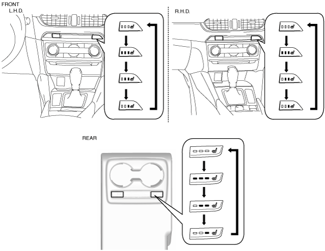
Switch display |
Temperature level |
Average temperature around seat warmer unit |
||
|---|---|---|---|---|
|
Front |
Rear |
Seat cushion side |
Seat back side |
|
 |
 |
0
|
—
|
|
 |
 |
1
|
Approx. 37°C {99 °F}
|
|
 |
 |
2
|
Approx. 40°C {104 °F}
|
Approx. 42°C {108 °F}
|
 |
 |
3
|
Approx. 42°C {108 °F}
|
Approx. 47°C {117 °F}
|
|
Temperature level
|
Average temperature around seat warmer unit (seat cushion side)
|
|||
|
Cloth type
|
Leather type
|
|||
|
Increase start temperature
|
Decrease start temperature
|
Increase start temperature
|
Decrease start temperature
|
|
|
0
|
—
|
|||
|
1
|
Approx. 23°C {73 °F}
|
Approx. 25°C {77 °F}
|
Approx. 23°C {73 °F}
|
Approx. 25°C {77 °F}
|
|
2
|
Approx. 32°C {90 °F}
|
Approx. 34°C {93 °F}
|
Approx. 30°C {86 °F}
|
Approx. 32°C {90 °F}
|
|
3
|
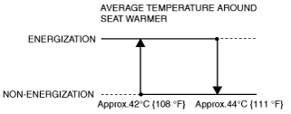
Approx. 42°C {108 °F}
|
Approx. 44°C {111 °F}
|
Approx. 38°C {100 °F}
|
Approx. 40°C {104 °F}
|
Ex.) Cloth-type temperature level is 3:
am6zzn00004095
|
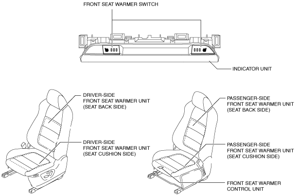
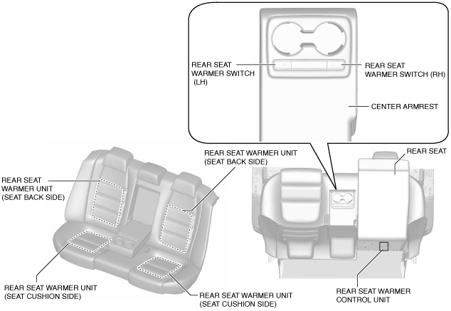
Structural view
Front
am6zzn00004393
|
Rear
am6zzn00004096
|
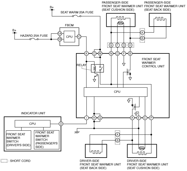
System wiring diagram
Front
am6zzn00004097
|
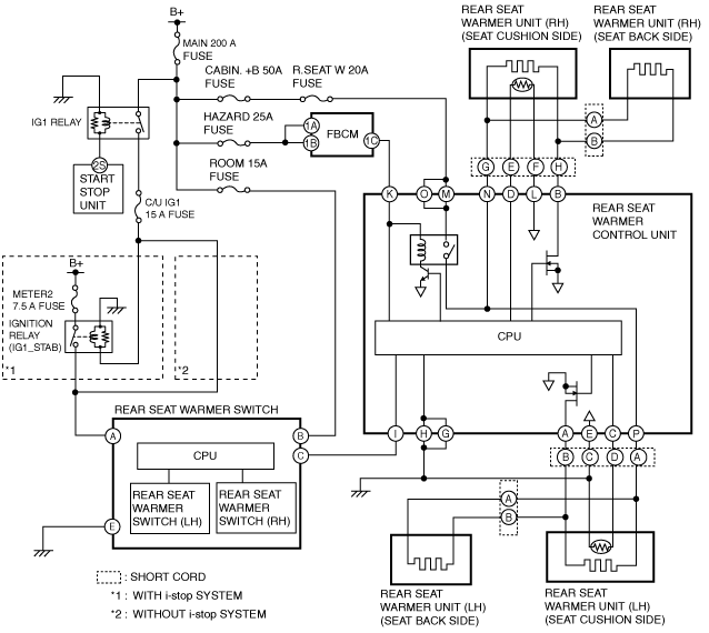
Rear
am6zzn00004098
|
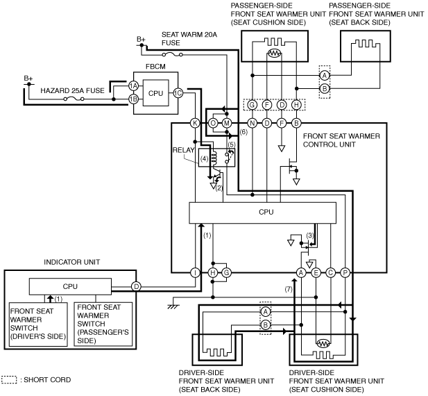
Operation
Front
1. When the indicator unit detects the front seat warmer switch (driver’s side) operation, it sends (1) a switch operation signal (temperature level “3”) to the CPU of the front seat warmer control unit.
2. When the CPU of the front seat warmer control unit receives the switch operation signal (temperature level “3”) from the indicator unit, it sends current to the transistor to turn it on (2).
3. Current flows (3) to the FET by turning the transistor on.
4. The current flows (4) to the relay coil to turn the relay switch on (5).
5. When the relay switch is turned on, the ground circuit is established and the current flows (6) to the front seat warmer unit in the driver’s side seat cushion and front seat back.
6. The heating wire warms up (7) by the current sent to the front seat warmer unit in the driver’s side front seat cushion and front seat back.
am6zzn00004099
|
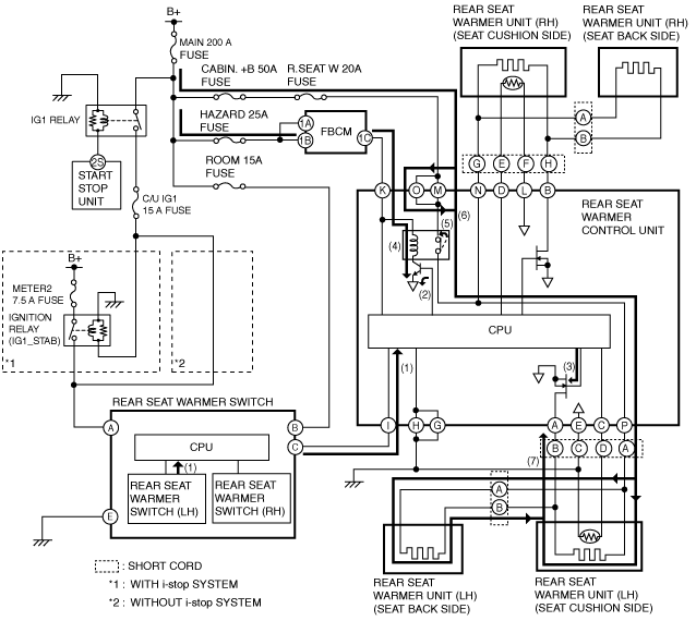
Rear
1. When the CPU of the rear seat warmer switch detects the rear seat warmer switch (LH) operation, it sends (1) a switch operation signal (temperature level “3”) to the CPU of the rear seat warmer control unit.
2. When the CPU of the rear seat warmer control unit receives the switch operation signal (temperature level “3”) from the rear seat warmer switch, it sends current to the transistor to turn it on (2).
3. Current flows (3) to the FET by turning the transistor on.
4. The current flows (4) to the relay coil to turn the relay switch on (5).
5. When the relay switch is turned on, the ground circuit is established and the current flows (6) to the rear seat warmer unit in the rear seat cushion (LH) and rear seat back (LH).
6. The heating wire warms up (7) by the current sent to the rear seat warmer unit in the rear seat cushion (LH) and rear seat back (LH).
am6zzn00004100
|
Fail-safe