 |
am6zzw00012762
REAR COMBINATION LIGHT REMOVAL/INSTALLATION
id091800801000
4SD
1. Disconnect the negative battery cable. (See NEGATIVE BATTERY CABLE DISCONNECTION/CONNECTION [SKYACTIV-G 2.0, SKYACTIV-G 2.5 (WITHOUT i-stop)].) (See NEGATIVE BATTERY CABLE DISCONNECTION/CONNECTION [SKYACTIV-G 2.0, SKYACTIV-G 2.5].) (See NEGATIVE BATTERY CABLE DISCONNECTION/CONNECTION [SKYACTIV-D 2.2].)
2. Remove the following parts:
3. Partially peel back the trunk side trim. (See TRUNK SIDE TRIM REMOVAL/INSTALLATION.)
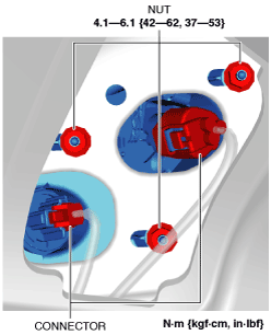
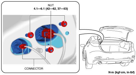
4. Disconnect the connectors.
am6zzw00012762
|
5. Remove the nuts.
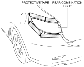
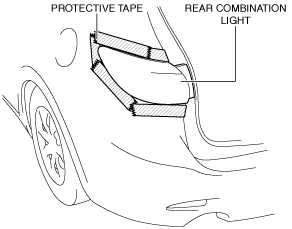
6. To prevent scratches or damage, affix protective tape to the position shown in the figure.
am6zzw00009288
|
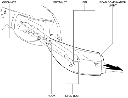
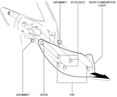
7. Pull the rear combination light in the direction of the arrow shown in the figure and pull out pins, stud bolts and hook from the body. (See Grommet Installation Note.)
am6zzw00012763
|
8. Remove the rear combination light.
9. Install in the reverse order of removal.
WGN
1. Disconnect the negative battery cable. (See NEGATIVE BATTERY CABLE DISCONNECTION/CONNECTION [SKYACTIV-G 2.0, SKYACTIV-G 2.5 (WITHOUT i-stop)].) (See NEGATIVE BATTERY CABLE DISCONNECTION/CONNECTION [SKYACTIV-G 2.0, SKYACTIV-G 2.5].) (See NEGATIVE BATTERY CABLE DISCONNECTION/CONNECTION [SKYACTIV-D 2.2].)
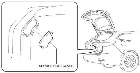
2. Remove the service hole cover.
am6zzw00009290
|
3. Disconnect the connectors.
am6zzw00012764
|
4. Remove the nuts.
5. To prevent scratches or damage, affix protective tape to the position shown in the figure.
am6zzw00009292
|
6. Pull the rear combination light in the direction of the arrow shown in the figure and pull out pins, stud bolts and hook from the body. (See Grommet Installation Note.)
am6zzw00012765
|
7. Remove the rear combination light.
8. Install in the reverse order of removal.
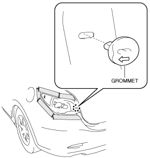
Grommet Installation Note
1. Install the grommet with the arrow pointed outward the vehicle.
am6zzw00012766
|