 |
am6zzw00012811
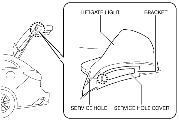
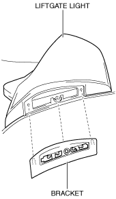
LIFTGATE LIGHT REMOVAL/INSTALLATION
id091800812600
1. Disconnect the negative battery cable. (See NEGATIVE BATTERY CABLE DISCONNECTION/CONNECTION [SKYACTIV-G 2.0, SKYACTIV-G 2.5 (WITHOUT i-stop)].) (See NEGATIVE BATTERY CABLE DISCONNECTION/CONNECTION [SKYACTIV-G 2.0, SKYACTIV-G 2.5].) (See NEGATIVE BATTERY CABLE DISCONNECTION/CONNECTION [SKYACTIV-D 2.2].)
2. Remove the following parts:
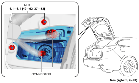
3. Disconnect the connectors.
am6zzw00012811
|
4. Remove the nuts.
5. Insert a flathead screwdriver into the service hole in the position shown in the figure.
am6zzw00009245
|
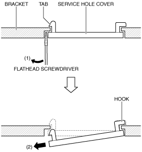
6. Move the flathead screwdriver in the direction of the arrow (1) shown in the figure to detach the service hole cover tab from the bracket.
am6zzw00009246
|
7. Pull out the service hole cover in the direction of the arrow (2) shown in the figure and pull out the service hole cover hook from the bracket.
8. Remove the service hole cover.
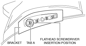
9. Insert the flathead screwdriver into the clearance between the bracket tab A and the liftgate light shown in the figure.
am6zzw00009247
|
10. Move the flathead screwdriver in the direction of arrow (1) shown in the figure to press the tab A, and pull the bracket in the direction of arrow (2) to detach the tab A from the liftgate light.
am6zzw00012812
|
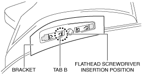
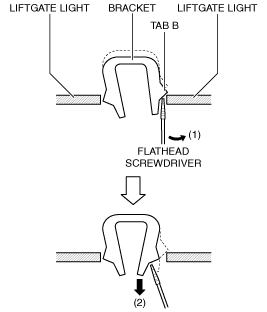
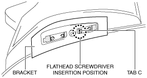
11. Insert the flathead screwdriver into the clearance between the bracket tab B and the liftgate light shown in the figure.
am6zzw00009249
|
12. Move the flathead screwdriver in the direction of arrow (1) shown in the figure to press the tab B, and pull the bracket in the direction of arrow (2) to detach the tab B from the liftgate light.
am6zzw00012813
|
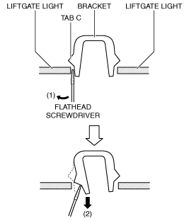
13. Insert the flathead screwdriver into the clearance between the bracket tab C and the liftgate light shown in the figure.
am6zzw00009251
|
14. Move the flathead screwdriver in the direction of arrow (1) shown in the figure to press the tab C, and pull the bracket in the direction of arrow (2) to detach the tab C from the liftgate light.
am6zzw00012814
|
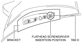
15. Insert the flathead screwdriver into the clearance between the bracket tab D and the liftgate light shown in the figure.
am6zzw00009253
|
16. Move the flathead screwdriver in the direction of arrow (1) shown in the figure to press the tab D, and pull the bracket in the direction of arrow (2) to detach the tab D from the liftgate light.
am6zzw00012815
|
17. Remove the bracket.
am6zzw00011295
|
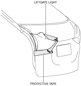
18. To prevent scratches or damage, affix protective tape to the position shown in the figure.
am6zzw00009256
|
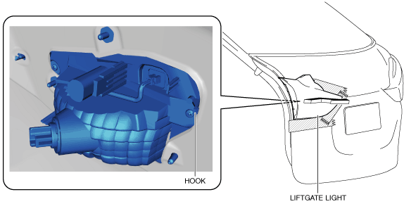
19. Move the liftgate light in the direction of the arrow shown in the figure to pull out the hook from the liftgate.
am6zzw00012816
|
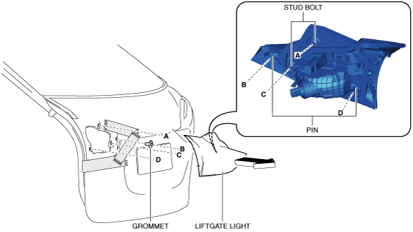
20. Pull the liftgate light in the direction of the arrow shown in the figure and pull out the pins and stud bolts from the liftgate.
am6zzw00012817
|
21. Remove the liftgate light.
22. Install in the reverse order of removal.