 |
am6zzw00013588
COMMANDER SWITCH REMOVAL/INSTALLATION
id092000811300
1. Disconnect the negative battery cable. (See NEGATIVE BATTERY CABLE DISCONNECTION/CONNECTION [SKYACTIV-D 2.2].) (See NEGATIVE BATTERY CABLE DISCONNECTION/CONNECTION [SKYACTIV-G 2.0, SKYACTIV-G 2.5].) (See NEGATIVE BATTERY CABLE DISCONNECTION/CONNECTION [SKYACTIV-G 2.0, SKYACTIV-G 2.5 (WITHOUT i-stop)].)
2. Remove the upper panel. (See UPPER PANEL REMOVAL/INSTALLATION.)
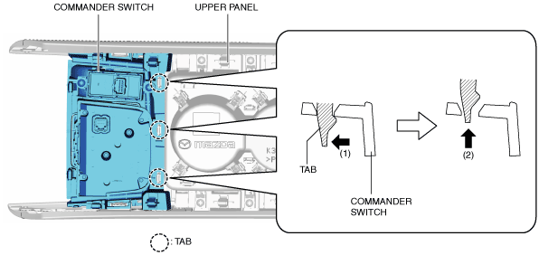
3. While pressing the tabs of the clip in the direction of arrow (1) shown in the figure, press it in the direction of arrow (2) to detach the upper panel tabs from the commander switch.
am6zzw00013588
|
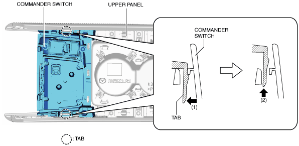
4. While pressing the tabs of the upper panel in the direction of the arrows (1) shown in the figure, press the upper panel in the direction of the arrow (2) to detach the tabs of the upper panel from the commander switch.
am6zzw00013589
|
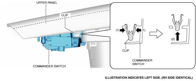
5. While pressing the tabs of the upper panel in the direction of the arrows (1) shown in the figure, press the upper panel in the direction of the arrow (2) to detach the tabs of the upper panel from the commander switch.
am6zzw00013590
|
6. Remove the commander switch.
7. Install in the reverse order of removal.