 |
am6zzw00009104
RELAY INSPECTION
id092100800300
Relay Type
|
Connector type |
Part name |
|---|---|
|
Type A
|
• Electric AT oil pump relay
• A/C relay
• Headlight HI relay
• Headlight LO relay
• Outlet relay
• Horn relay
• ACC relay
• Cooling fan relay No.1 (SKYACTIV-G 2.0, SKYACTIV-G 2.5)
• Cooling fan relay No.2 (SKYACTIV-G 2.0, SKYACTIV-G 2.5)
• Ignition relay (ACC_STAB) (SKYACTIV-D 2.2)
• Headlight LO relay (RH)
• Rear window defogger relay
• Front fog light relay
• Starter relay (Without i-stop system)
• Ignition relay (ACC_STAB) (SKYACTIV-G 2.0, SKYACTIV-G 2.5)
• Ignition relay (IG1_STAB)
|
|
Type B
|
• Brake light relay
• Cooling fan relay No.3 (SKYACTIV-G 2.0, SKYACTIV-G 2.5)
|
|
Type C
|
• Blower relay
• Cooling fan relay No.2 (SKYACTIV-D 2.2)
• Cooling fan relay No.1 (SKYACTIV-D 2.2)
|
|
Type D
|
• Fuel injector relay (SKYACTIV-G 2.0, SKYACTIV-G 2.5)
• Check connector (SKYACTIV-D 2.2)
• Fuel pump relay
• IG1 relay
• Electric variable valve timing relay (SKYACTIV-G 2.0, SKYACTIV-G 2.5)
• Blow-by heater relay (SKYACTIV-D 2.2)
• Main relay
|
|
Type E
|
Starter relay (With i-stop system)
|
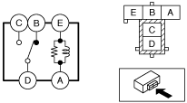
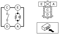
Type A
1. Remove the relay. (See RELAY LOCATION.)
2. Verify the continuity between relay terminals C and D.
am6zzw00009104
|
3. Verify the continuity between relay terminals E and A.
4. Apply battery voltage to relay terminal E, and connect terminal A to ground.
5. Verify the continuity between relay terminals C and D.
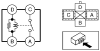
Type B
1. Remove the relay. (See RELAY LOCATION.)
2. Verify the continuity between relay terminals C and D.
ac5wzw00000084
|
3. Verify the continuity between the relay terminals E and A.
4. Verify the continuity between the relay terminals B and D.
5. Apply battery voltage to relay terminal E, and connect terminal A to ground.
6. Verify the continuity between relay terminals C and D.
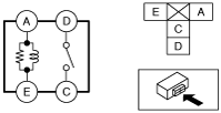
Type C
1. Remove the relay. (See RELAY LOCATION.)
2. Verify the continuity between the relay terminals C and A.
ac5wzw00000085
|
3. Verify the continuity between the relay terminals D and B.
4. Apply battery voltage to relay terminal D, and connect terminal B to ground.
5. Verify the continuity between relay terminals C and A.
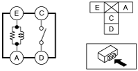
Type D
1. Remove the relay. (See RELAY LOCATION.)
2. Verify the continuity between relay terminals D and C.
ac5wzw00000086
|
3. Verify the continuity between relay terminals A and E.
4. Apply battery voltage to relay terminal A, and connect terminal E to ground.
5. Verify the continuity between relay terminals D and C.
Type E
1. Remove the relay. (See RELAY LOCATION.)
2. Verify the continuity between relay terminals C and D.
am6zzw00009105
|
3. Verify the continuity between relay terminals E and A.
4. Apply battery voltage to relay terminal E, and connect terminal A to ground.
5. Verify the continuity between relay terminals C and D.