MULTIPLEX COMMUNICATION SYSTEM


id100000001400


Outline

•  A control area network (CAN) system has been adopted in which the multiple control modules send/receive signals using two common communication lines.
•  Local CAN, ISO communication, or LIN communication has been adopted for the individual communication between control modules in consideration of the communication speed and the cost.

System Wiring Diagram

Note
•  The following figure shows the CAN/LIN communication/ISO communication/local CAN connection conditions. The availability of the equipment may differ depending on the vehicle specifications.

L.H.D.

am6zzn00005151

R.H.D.

am6zzn00004900

Local CAN

am6zzn00004901

Structural View

Note
•  The following figure shows the installation positions for the equipment which perform CAN communication. The availability of the equipment may differ depending on the vehicle specifications.

L.H.D.

am6zzn00005152

R.H.D.

am6zzn00004903

Function


CAN (controller area network) system

•  HS-CAN (high-speed controller area network) is used for communication between the following modules:
―  PCM
―  DSC HU/CM
―  Radar unit (With smart brake support (SBS))
―  TCM (ATX)
―  Front body control module (FBCM)
―  Adaptive front lighting system (AFS) control module/auto leveling control module (With headlight auto leveling system)
―  DC-DC converter (i-ELOOP) (With i-ELOOP)
―  4WD control module (4WD)
―  Position memory control module (With memory power seat)
―  Electric parking brake control module
―  Audio amplifier (With Bose® type audio)
―  Forward sensing camera (FSC) (With forward sensing camera (FSC))
―  EPS control module
―  Mazda ERA-GLONASS control module (With Mazda ERA-GLONASS)
―  Start stop unit
―  Connectivity master unit (CMU) (With center display)
―  SAS control module
―  Instrument cluster
•  MS-CAN (mid-speed controller area network) is used for communication between the following modules:
―  Instrument cluster
―  Parking assist unit (With parking sensor system)
―  Climate control unit
―  Rear body control module (RBCM)
―  Rear mount camera (With rear mount camera (Predicted vehicle path assist lines display type))
―  Blind spot monitoring (BSM) control module (LH) (With blind spot monitoring (BSM) system)


Local CAN

•  Local CAN is used for communication between the following modules:
―  Between PCM and TCM
―  Between connectivity master unit (CMU), CD player/DVD/CD player, and tuner and amp unit (TAU)
―  Between audio unit, Bluetooth® unit, and CD player
―  Between blind spot monitoring (BSM) control module (LH) and blind spot monitoring (BSM) control module (RH)


LIN communication

•  LIN communication is used for communication between the following modules:
―  Between front body control module (FBCM) and auto light sensor/rain sensor/humidity sensor
―  Between front body control module (FBCM) and current sensor
―  Between front body control module (FBCM) and DC-DC converter
―  Between adaptive front lighting system (AFS) control module and swivel actuator (LH)
―  Between adaptive front lighting system (AFS) control module and swivel actuator (RH)
―  Between connectivity master unit (CMU) and commander switch
―  Between rear body control module (RBCM) and intruder sensor
―  Between rear body control module (RBCM) and theft-deterrent siren


ISO communication

•  ISO communication is used for communication between the following modules:
―  Between rear body control module (RBCM) and start stop unit
―  Between rear body control module (RBCM) and power window main switch


Construction


CAN

•  The HS-CAN has terminator resistors built into the following units which form the CAN lines.
―  Between PCM terminals 2AK (CAN_H) and 2AL (CAN_L)
―  Between instrument cluster terminals B (CAN_H) and D (CAN_L)
•  The MS-CAN has terminal resistors built into the following units which form the CAN lines.
―  Between rear body control module (RBCM) terminals 3E (CAN_H) and 3G (CAN_L)
―  Between instrument cluster terminals C (CAN_H) and E (CAN_L)


Local CAN

•  The local CAN has terminator resistors built into the following units which form the CAN lines.
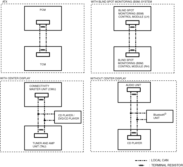
―  Between PCM terminals 1A (CAN_H) and 1B (CAN_L) (SKYACTIV-G 2.0, SKYACTIV-G 2.5)
―  Between PCM terminals 1AD (CAN_H) and 1Y (CAN_L) (SKYACTIV-D 2.2)
―  Between TCM terminals G (CAN_H) and H (CAN_L)
―  Between audio unit terminals 1O (CAN_H) and 1Q (CAN_L)
―  Between CD player terminals G (CAN_H) and H (CAN_L) (Without center display)
―  Between connectivity master unit (CMU) terminals 2I (CAN_H) and 2J (CAN_L)
―  Between tuner and amp unit (TAU) terminals 2O (CAN_H) and 2Q (CAN_L) (L.H.D.)
―  Between tuner and amp unit (TAU) terminals 1AA (CAN_H) and 1AB (CAN_L) (R.H.D.)
―  Between blind spot monitoring (BSM) control module (LH) terminals A (CAN_H) and B (CAN_L) (Australian specs.)
―  Between blind spot monitoring (BSM) control module (RH) terminals A (CAN_H) and B (CAN_L) (Australian specs.)
―  Between blind spot monitoring (BSM) control module (LH) terminals G (CAN_H) and J (CAN_L) (Except Australian specs.)
―  Between blind spot monitoring (BSM) control module (RH) terminals G (CAN_H) and J (CAN_L) (Except Australian specs.)


LIN communication

•  The LIN communication has drivers built into the following units which form the LIN communication lines.
―  Front body control module (FBCM)
―  Auto light sensor/rain sensor/humidity sensor
―  Current sensor
―  DC-DC converter
―  Adaptive front lighting system (AFS) control module
―  Swivel actuator (LH)
―  Swivel actuator (RH)
―  Connectivity master unit (CMU)
―  Commander switch
―  Rear body control module (RBCM)
―  Intruder sensor
―  Theft-deterrent siren


ISO communication

•  The ISO communication has drivers built into the following units which form the ISO communication lines.
―  Rear body control module (RBCM)
―  Start stop unit
―  Power window main switch