GENERATOR CONTROL [SKYACTIV-G 2.0, SKYACTIV-G 2.5]


id0140g2208900

Note
•  The generator output control is different whether the i-ELOOP is equipped or not. (See Without i-ELOOP.) (See With i-ELOOP.)

Without i-ELOOP


Outline

•  To assure Idling stability, controls the generator output voltage to the optimum amount according to the engine operation and electrical load conditions.
•  The PCM determines the engine operation and electrical load conditions based on the input signals from each control part. It then uses this information to control the energization time of the generator field coils.


Block diagram

am3zzn00005223


Operation

Determination method for target excitation current
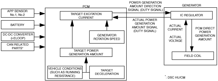
•  Calculates the target excitation current according to the generator target output amount and the generator rotation speed.
•  The generator target output amount is calculated according to the target battery voltage and battery voltage. (vehicles without current sensor)
•  Calculates the generator target output amount according to the driving conditions, electrical load and the power storage device conditions. If the current sensor is malfunctioning, the target output amount is calculated according to the target battery voltage and battery voltage. (vehicles with current sensor)
•  During deceleration fuel-cut, the PCM increases the generator output amount and stores electricity in the battery. In conditions other than deceleration, only the required amount of electricity is charged according to the battery status to lower the load on the generator.
Determination method for field coil excitation time
•  The PCM increases or decreases the field coil excitation current by sending a duty signal to the power transistor built into the generator.
•  The field coil energization current changes according to changes in the power transistor excitation time. This is accomplished by changing the duty signal duty ratio. For example, when the battery positive voltage drops, the duty ratio of the duty signal sent to the power transistor is larger, increasing the field coil excitation current.
am3zzn00003648


With i-ELOOP


Outline

•  Idling stability has been improved by optimum control of the generator voltage according to the engine operation and electrical load conditions.
•  The PCM controls the variable voltage type generator so that the driver does not sense strangeness in the deceleration from the power generation torque produced during deceleration.


Block diagram

amxzzn00001150


Operation

•  The PCM increases/decreases the field coil excitation current and controls the power generation amount of the generator by calculating the target excitation current and sending a power generation amount signal (duty signal) to the IC regulator.
Determination method for target excitation current
•  The PCM determines the generator target power generation amount based on the vehicle conditions (such as the running resistance) and the result of the estimated target deceleration*1.
•  Calculates the target excitation current based on the target power generation amount and the generator rotation speed.
*1  :The PCM calculates the target deceleration during regenerative braking according to the vehicle speed and acceleration and brake operations so that the driver does not sense strangeness in the deceleration from the power generation torque produced during deceleration.
•  The PCM gradually increases the generator output voltage considering the actual power generation amount of the generator, and controls the generator at the specified value during regenerative deceleration. It performs feedback of the actual power generation amount of the generator to control the excitation current precisely.
•  For details on the i-ELOOP operation, refer to [i-ELOOP]. (See i-ELOOP [i-ELOOP].)