 |
am6zzw00014735
TIRE PRESSURE MONITORING SYSTEM SET SWITCH INSPECTION
id021200206000
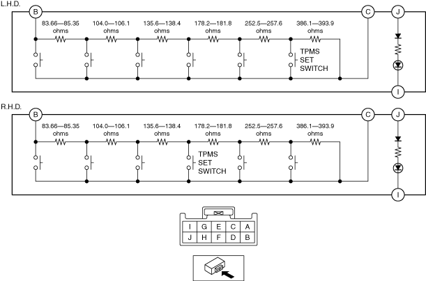
Resistance Inspection
1. Remove the TPMS set switch. (See CLUSTER SWITCH REMOVAL/INSTALLATION.)
2. Verify that the resistance between the TPMS set switch terminals B and C is as indicated in the table.
am6zzw00014735
|
TPMS set switch specification
|
Terminal |
Test condition |
Resistance (ohms) |
|---|---|---|
|
B—C
|
TPMS set switch pressed
|
L.H.D.:753.96—769.25
R.H.D.:323.26—329.85
|
|
All switches released
|
1140.06—1163.15
|
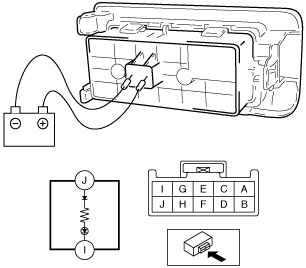
LED Illumination Inspection
1. Remove the TPMS set switch. (See CLUSTER SWITCH REMOVAL/INSTALLATION.)
2. Apply battery positive voltage to TPMS set switch terminal J, and connect terminal I to ground.
ac5jjw00000654
|
3. Verify that the LED illuminates.