am6zzw00008790
|
DSC HU/CM REMOVAL/INSTALLATION
id041500801000
1. Disconnect the negative battery cable. (See NEGATIVE BATTERY CABLE DISCONNECTION/CONNECTION [SKYACTIV-G 2.0, SKYACTIV-G 2.5].) (See NEGATIVE BATTERY CABLE DISCONNECTION/CONNECTION [SKYACTIV-G 2.0, SKYACTIV-G 2.5 (WITHOUT i-stop)].) (See NEGATIVE BATTERY CABLE DISCONNECTION/CONNECTION [SKYACTIV-D 2.2].)
2. For SKYACTIV-G 2.0 or SKYACTIV-G 2.5, remove the plug hole plate. (See PLUG HOLE PLATE REMOVAL/INSTALLATION [SKYACTIV-G 2.0, SKYACTIV-G 2.5].)
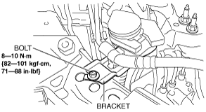
3. For SKYACTIV-D 2.2, perform the following procedure:
am6zzw00008790
|
4. Remove the bracket.
am6zzw00008791
|
5. Remove in the order indicated in the table.
6. Install in the reverse order of removal.
7. After installation, add brake fluid, bleed the air, and inspect for fluid leakage. (See BRAKE FLUID AIR BLEEDING.)
8. Perform the following procedure to implement the DSC HU/CM automatic configuration.
9. Perform the DSC related parts sensor initialization procedure (only when replacing it with a new one). (See DSC RELATED PARTS SENSOR INITIALIZATION PROCEDURE.)
10. Perform the TPMS initialization procedure. (Vehicles with TPMS) (See TIRE PRESSURE MONITORING SYSTEM INITIALIZATION PROCEDURE.)
11. Clear the DTCs from the memory. (See CLEARING DTC [DYNAMIC STABILITY CONTROL (DSC)].)
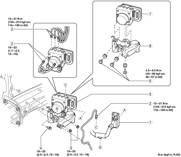
Vehicles without smart brake support (SBS) and smart city brake support (SCBS)
am6zzw00008899
|
|
1
|
Connector
(See Connector Removal Note.)
(See Connector Installation Note.)
|
|
2
|
Brake pipe
(See Brake Pipe Removal Note.)
(See Brake Pipe Installation Note.)
|
|
3
|
Nut
|
|
4
|
Bolt
|
|
5
|
DSC HU/CM component
|
|
6
|
Bolt
|
|
7
|
DSC HU/CM
|
|
8
|
Bracket
|
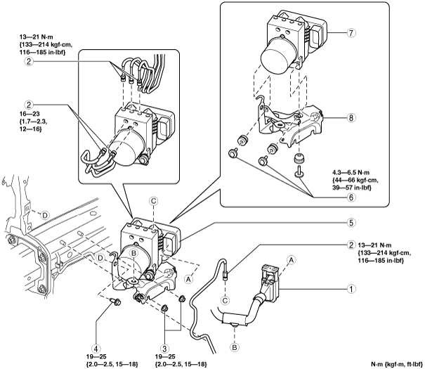
Vehicles with smart brake support (SBS) or smart city brake support (SCBS)
am6zzw00008900
|
|
1
|
Connector
(See Connector Removal Note.)
(See Connector Installation Note.)
|
|
2
|
Brake pipe
(See Brake Pipe Removal Note.)
(See Brake Pipe Installation Note.)
|
|
3
|
Nut
|
|
4
|
Bolt
|
|
5
|
DSC HU/CM component
|
|
6
|
Bolt
|
|
7
|
DSC HU/CM
|
|
8
|
Bracket
|
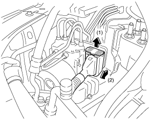
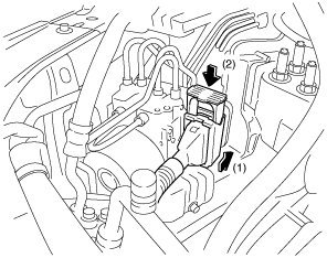
Connector Removal Note
1. Disconnect the connector in the order shown in the figure.
am6zzw00008792
|
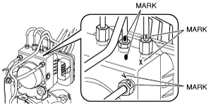
Brake Pipe Removal Note
1. Place an alignment mark on the brake pipe and DSC HU/CM.
am6zzw00008793
|
2. Apply protective tape to the connector to prevent brake fluid from entering.
3. Disconnect the brake pipes.
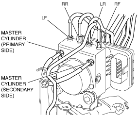
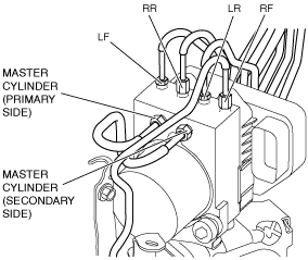
Brake Pipe Installation Note
1. Align the marks made before removal and install the brake pipe to the DSC HU/CM and brake pipe joint referring to the figure.
Vehicles without smart brake support (SBS) and smart city brake support (SCBS)
am6zzw00008794
|
Vehicles with smart brake support (SBS) or smart city brake support (SCBS)
am6zzw00008795
|
2. Tighten the brake pipe to the specified torque using the commercially available flare nut wrench.
Connector Installation Note
1. Connect the connector in the order shown in the figure.
am6zzw00008796
|
2. After connecting the connector, verify that the connector is completely locked.