 |
am6zzw00008272
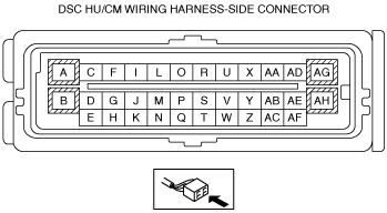
DSC HU/CM INSPECTION
id041500801100
1. Disconnect the DSC HU/CM connector. (See DSC HU/CM REMOVAL/INSTALLATION.)
2. Connect the negative battery cable. (See NEGATIVE BATTERY CABLE DISCONNECTION/CONNECTION [SKYACTIV-G 2.0, SKYACTIV-G 2.5 (WITHOUT i-stop)].) (See NEGATIVE BATTERY CABLE DISCONNECTION/CONNECTION [SKYACTIV-G 2.0, SKYACTIV-G 2.5].) (See NEGATIVE BATTERY CABLE DISCONNECTION/CONNECTION [SKYACTIV-D 2.2].)
3. Attach the tester lead to the DSC HU/CM wiring harness-side connector and inspect voltage, continuity, or resistance according to the standard (reference) on the table.
Standard (Reference)
am6zzw00008272
|
|
Terminal |
Signal name |
Connected to |
Measured item |
Measured terminal (measurement condition) |
Standard |
Inspection item(s) |
|---|---|---|---|---|---|---|
|
A
|
Ground (system)
|
Ground point
|
Continuity
|
A—ground point
|
Continuity detected
|
• Wiring harness (A—ground point)
|
|
B
|
Ground (pump motor)
|
Ground point
|
Continuity
|
B—ground point
|
Continuity detected
|
• Wiring harness (B—ground point)
|
|
C
|
Brake light (vehicles with smart brake support (SBS) or smart city brake support (SCBS))
|
Brake light relay*1 or brake light unit*2*3
|
Voltage
|
Brake pedal depressed
|
B+
|
• Wiring harness (C—Brake light relay terminal D or brake light unit terminal H)
|
|
Brake pedal not depressed
|
1 V or less
|
|||||
|
D
|
CAN_L
|
CAN module
|
This terminal is used for communication and cannot be used for malfunction determination during terminal voltage inspection. Perform a DTC inspection.
|
|||
|
E
|
CAN_H
|
CAN module
|
This terminal is used for communication and cannot be used for malfunction determination during terminal voltage inspection. Perform a DTC inspection.
|
|||
|
F
|
CAN2_L
|
SAS control module
|
This terminal is used for communication and cannot be used for malfunction determination during terminal voltage inspection. Perform a DTC inspection.
|
|||
|
G
|
CAN2_H
|
SAS control module
|
This terminal is used for communication and cannot be used for malfunction determination during terminal voltage inspection. Perform a DTC inspection.
|
|||
|
H
|
—
|
—
|
—
|
—
|
—
|
—
|
|
I
|
LR wheel-speed sensor (-)
|
LR ABS wheel-speed sensor
|
Continuity
|
I—LR ABS wheel-speed sensor terminal B
|
Continuity detected
|
• Wiring harness (I—LR ABS wheel-speed sensor terminal B)
|
|
J
|
RR wheel-speed sensor (-)
|
RR ABS wheel-speed sensor
|
Continuity
|
J—RR ABS wheel-speed sensor terminal B
|
Continuity detected
|
• Wiring harness (J—RR ABS wheel-speed sensor terminal B)
|
|
K
|
—
|
—
|
—
|
—
|
—
|
—
|
|
L
|
LR wheel-speed sensor (+)
|
LR ABS wheel-speed sensor
|
Continuity
|
L—LR ABS wheel-speed sensor terminal A
|
Continuity detected
|
• Wiring harness (L—LR ABS wheel-speed sensor terminal A)
|
|
M
|
RR wheel-speed sensor (+)
|
RR ABS wheel-speed sensor
|
Continuity
|
M—RR ABS wheel-speed sensor terminal A
|
Continuity detected
|
• Wiring harness (M—RR ABS wheel-speed sensor terminal A)
|
|
N
|
—
|
—
|
—
|
—
|
—
|
—
|
|
O
|
RF wheel-speed sensor (-)
|
RF ABS wheel-speed sensor
|
Continuity
|
O—RF ABS wheel-speed sensor terminal B
|
Continuity detected
|
• Wiring harness (O—RF ABS wheel-speed sensor terminal B)
|
|
P
|
LF wheel-speed sensor (-)
|
LF ABS wheel-speed sensor
|
Continuity
|
P—LF ABS wheel-speed sensor terminal B
|
Continuity detected
|
• Wiring harness (P—LF ABS wheel-speed sensor terminal B)
|
|
Q
|
—
|
—
|
—
|
—
|
—
|
—
|
|
R
|
RF wheel-speed sensor (+)
|
RF ABS wheel-speed sensor
|
Continuity
|
R—RF ABS wheel-speed sensor terminal A
|
Continuity detected
|
• Wiring harness (R—RF ABS wheel-speed sensor terminal A)
|
|
S
|
LF wheel-speed sensor (+)
|
LF ABS wheel-speed sensor
|
Continuity
|
S—LF ABS wheel-speed sensor terminal A
|
Continuity detected
|
• Wiring harness (S—LF ABS wheel-speed sensor terminal A)
|
|
T
|
—
|
—
|
—
|
—
|
—
|
—
|
|
U
|
—
|
—
|
—
|
—
|
—
|
—
|
|
V
|
—
|
—
|
—
|
—
|
—
|
—
|
|
W
|
—
|
—
|
—
|
—
|
—
|
—
|
|
X
|
—
|
—
|
—
|
—
|
—
|
—
|
|
Y
|
—
|
—
|
—
|
—
|
—
|
—
|
|
Z
|
—
|
—
|
—
|
—
|
—
|
—
|
|
AA
|
—
|
—
|
—
|
—
|
—
|
—
|
|
AB
|
—
|
—
|
—
|
—
|
—
|
—
|
|
AC
|
—
|
—
|
—
|
—
|
—
|
—
|
|
AD
|
—
|
—
|
—
|
—
|
—
|
—
|
|
AE
|
—
|
—
|
—
|
—
|
—
|
—
|
|
AF
|
Power supply (system)
|
Ignition switch
|
Voltage
|
Ignition switched ON (engine off).
|
B+
|
• Wiring harness (AF—ignition switch)
|
|
Switch the ignition to off.
|
1 V or less
|
|||||
|
AG
|
Power supply
(solenoid operation)
|
Battery
|
Voltage
|
Under any condition
|
B+
|
• Wiring harness (AG—battery)
|
|
AH
|
Power supply
(pump motor operation)
|
Battery
|
Voltage
|
Under any condition
|
B+
|
• Wiring harness (AH—battery)
|