 |
am6xuw00007948
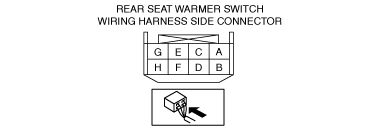
REAR SEAT WARMER SWITCH INSPECTION
id091300855500
1. Remove the rear seat warmer switch. (See REAR SEAT WARMER SWITCH REMOVAL/INSTALLATION.)
2. Verify that the voltages of each of the terminals are as indicated in the terminal voltage table (reference).
Terminal Voltage Table (Reference)
am6xuw00007948
|
|
Terminal |
Signal |
Connected to |
Measurement conditions |
Voltage (V) |
Inspection item(s) |
|
|---|---|---|---|---|---|---|
|
A
|
IG1
|
• Ignition relay (IG1_STAB)*1
• IG1 realy*2
|
Ignition switch ON (engine off or on)
|
B+
|
• Ignition relay (IG1_STAB)*1
• IG1 realy*2
|
|
|
Ignition switched OFF (LOCK)
|
1.0 or less
|
|||||
|
B
|
Power supply
|
ROOM 15 A fuse
|
Under any condition
|
B+
|
ROOM 15 A fuse
|
|
|
C
|
Rear seat warmer signal
|
Rear seat warmer control unit
|
Because this terminal is for communication, determination using terminal voltage inspection is not possible.
|
|||
|
D
|
Instrument cluster signal
|
Instrument cluster signal
|
Because this terminal is for communication, determination using terminal voltage inspection is not possible.
|
|||
|
E
|
GND
|
Body ground
|
Under any condition
|
1.0 or less
|
Body ground
|
|
|
F
|
—
|
—
|
—
|
—
|
—
|
|
|
G
|
—
|
—
|
—
|
—
|
—
|
|
|
H
|
—
|
—
|
—
|
—
|
—
|
|