 |
am6zzw00013561
TUNER AND AMP UNIT (TAU) REMOVAL/INSTALLATION
id092000031200
L.H.D.
1. Disconnect the negative battery cable. (See NEGATIVE BATTERY CABLE DISCONNECTION/CONNECTION [SKYACTIV-D 2.2].) (See NEGATIVE BATTERY CABLE DISCONNECTION/CONNECTION [SKYACTIV-G 2.0, SKYACTIV-G 2.5].) (See NEGATIVE BATTERY CABLE DISCONNECTION/CONNECTION [SKYACTIV-G 2.0, SKYACTIV-G 2.5 (WITHOUT i-stop)].)
2. Remove the following parts:
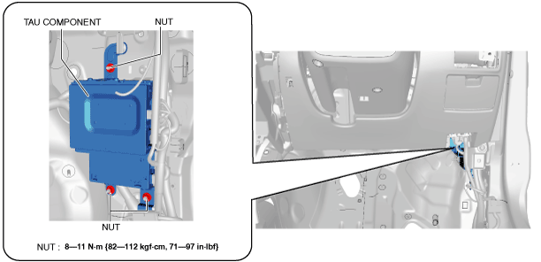
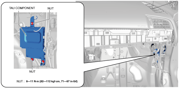
3. Remove the nuts.
am6zzw00013561
|
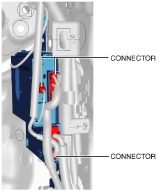
4. Disconnect the connectors.
am6zzw00013562
|
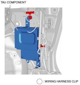
5. Pull out the wiring harness clip.
am6zzw00013563
|
6. Remove the tuner and amp unit (TAU) component.
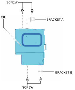
7. Remove the screws.
am6zzw00013564
|
8. Remove the brackets A and B.
9. Install in the reverse order of removal.
R.H.D.
1. Disconnect the negative battery cable. (See NEGATIVE BATTERY CABLE DISCONNECTION/CONNECTION [SKYACTIV-D 2.2].) (See NEGATIVE BATTERY CABLE DISCONNECTION/CONNECTION [SKYACTIV-G 2.0, SKYACTIV-G 2.5].) (See NEGATIVE BATTERY CABLE DISCONNECTION/CONNECTION [SKYACTIV-G 2.0, SKYACTIV-G 2.5 (WITHOUT i-stop)].)
2. Remove the following parts:
3. Remove the nuts.
am6zzw00013565
|
4. Disconnect the connectors.
am6zzw00013562
|
5. Pull out the wiring harness clip.
am6zzw00013563
|
6. Remove the tuner and amp unit (TAU) component.
7. Remove the screws.
am6zzw00013564
|
8. Remove the brackets A and B.
9. Install in the reverse order of removal.