ANTENNA FEEDER NO.2 INSPECTION
id092000812500
4SD
Without center display
1. Disconnect the negative battery cable. (See NEGATIVE BATTERY CABLE DISCONNECTION/CONNECTION [SKYACTIV-D 2.2].) (See NEGATIVE BATTERY CABLE DISCONNECTION/CONNECTION [SKYACTIV-G 2.0, SKYACTIV-G 2.5].) (See NEGATIVE BATTERY CABLE DISCONNECTION/CONNECTION [SKYACTIV-G 2.0, SKYACTIV-G 2.5 (WITHOUT i-stop)].)
2. Remove the following parts:
- (1) A-pillar trim (RH) (See A-PILLAR TRIM REMOVAL/INSTALLATION.)
- (2) Rear scuff plate (RH) (See REAR SCUFF PLATE REMOVAL/INSTALLATION.)
- (3) Rear seat cushion (RH) (See REAR SEAT CUSHION REMOVAL/INSTALLATION.)
- (4) Rear seat side back (RH) (See REAR SEAT SIDE BACK REMOVAL/INSTALLATION.)
- (5) Tire house trim (RH) (See TIRE HOUSE TRIM REMOVAL/INSTALLATION.)
- (6) C-pillar trim (RH) (See C-PILLAR TRIM REMOVAL/INSTALLATION.)
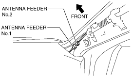
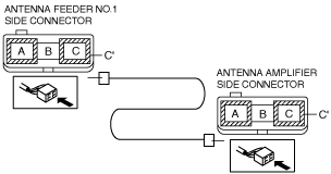
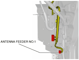
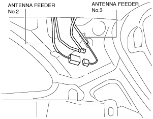
3. Disconnect antenna feeder No.1.
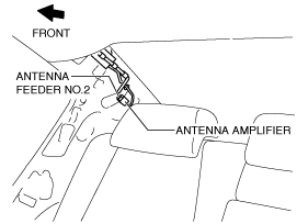
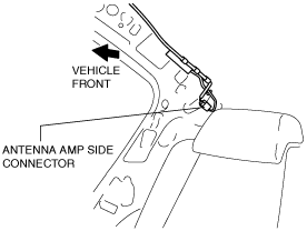
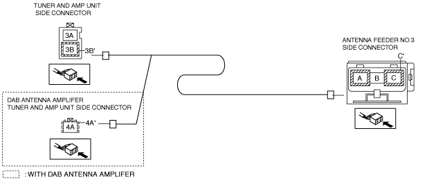
4. Disconnect antenna amplifier.
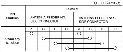
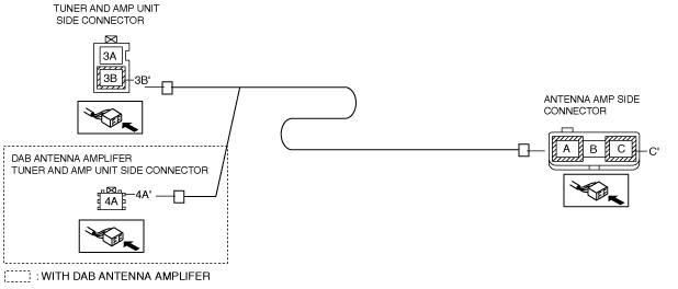
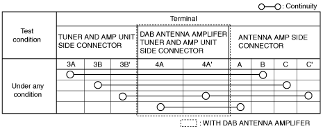
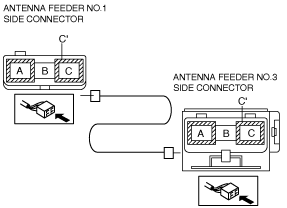
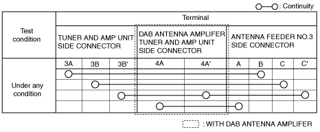
5. Verify that the continuity between antenna feeder No.2 terminals is as indicated in the table.
-
• If not as indicated in the table, replace antenna feeder No.2.
With center display
1. Disconnect the negative battery cable. (See NEGATIVE BATTERY CABLE DISCONNECTION/CONNECTION [SKYACTIV-D 2.2].) (See NEGATIVE BATTERY CABLE DISCONNECTION/CONNECTION [SKYACTIV-G 2.0, SKYACTIV-G 2.5].) (See NEGATIVE BATTERY CABLE DISCONNECTION/CONNECTION [SKYACTIV-G 2.0, SKYACTIV-G 2.5 (WITHOUT i-stop)].)
2. Remove the following parts:
- (1) Sunroof seaming welt (See SUNROOF UNIT REMOVAL/INSTALLATION.)
- (2) A pillar trim (See A-PILLAR TRIM REMOVAL/INSTALLATION.)
- (3) Sunvisor (See SUNVISOR REMOVAL/INSTALLATION.)
- (4) Front map light (See MAP LIGHT REMOVAL/INSTALLATION.)
- (5) Assist handle (See ASSIST HANDLE REMOVAL/INSTALLATION.)
- (6) Front scuff plate (See FRONT SCUFF PLATE REMOVAL/INSTALLATION.)
- (7) Front side trim (RH) (See FRONT SIDE TRIM REMOVAL/INSTALLATION.)
- (8) Rear scuff plate (See REAR SCUFF PLATE REMOVAL/INSTALLATION.)
- (9) B-pillar lower trim (See B-PILLAR LOWER TRIM REMOVAL/INSTALLATION.)
- (10) Front seat belt adjuster cover (See FRONT SEAT BELT REMOVAL/INSTALLATION.)
- (11) Upper anchor installation bolt on the seat belt (See FRONT SEAT BELT REMOVAL/INSTALLATION.)
- (12) B-pillar upper trim (See B-PILLAR UPPER TRIM REMOVAL/INSTALLATION.)
- (13) Rear seat cushion (See REAR SEAT CUSHION REMOVAL/INSTALLATION.)
- (14) Rear seat side back (See REAR SEAT SIDE BACK REMOVAL/INSTALLATION.)
- (15) Tire house trim (See TIRE HOUSE TRIM REMOVAL/INSTALLATION.)
- (16) C-pillar trim (See C-PILLAR TRIM REMOVAL/INSTALLATION.)
3. Disconnect antenna feeder No.1.
4. Disconnect antenna amplifier.
5. Verify that the continuity between antenna feeder No.2 terminals is as indicated in the table.
-
WGN
Without center display
1. Disconnect the negative battery cable. (See NEGATIVE BATTERY CABLE DISCONNECTION/CONNECTION [SKYACTIV-D 2.2].) (See NEGATIVE BATTERY CABLE DISCONNECTION/CONNECTION [SKYACTIV-G 2.0, SKYACTIV-G 2.5].) (See NEGATIVE BATTERY CABLE DISCONNECTION/CONNECTION [SKYACTIV-G 2.0, SKYACTIV-G 2.5 (WITHOUT i-stop)].)
2. Remove the following parts:
- (1) A-pillar trim (RH) (See A-PILLAR TRIM REMOVAL/INSTALLATION.)
- (2) Trunk board (See TRUNK BOARD REMOVAL/INSTALLATION.)
- (3) Trunk side pocket (RH) (See TRUNK SIDE POCKET REMOVAL/INSTALLATION.)
- (4) Trunk end trim (RH) (See TRUNK END TRIM REMOVAL/INSTALLATION.)
3. Partially peel back the trunk side upper trim. (See TRUNK SIDE UPPER TRIM REMOVAL/INSTALLATION.)
4. Remove the D-pillar trim (RH) (See D-PILLAR TRIM REMOVAL/INSTALLATION.)
5. Disconnect antenna feeder No.1.
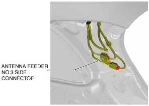
6. Disconnect antenna feeder No.3.
7. Verify that the continuity between antenna feeder No.2 terminals is as indicated in the table.
-
With center display
1. Disconnect the negative battery cable. (See NEGATIVE BATTERY CABLE DISCONNECTION/CONNECTION [SKYACTIV-D 2.2].) (See NEGATIVE BATTERY CABLE DISCONNECTION/CONNECTION [SKYACTIV-G 2.0, SKYACTIV-G 2.5].) (See NEGATIVE BATTERY CABLE DISCONNECTION/CONNECTION [SKYACTIV-G 2.0, SKYACTIV-G 2.5 (WITHOUT i-stop)].)
2. Remove the following parts:
- (1) Sunroof seaming welt (See SUNROOF UNIT REMOVAL/INSTALLATION.)
- (2) A pillar trim (See A-PILLAR TRIM REMOVAL/INSTALLATION.)
- (3) Sunvisor (See SUNVISOR REMOVAL/INSTALLATION.)
- (4) Front map light (See MAP LIGHT REMOVAL/INSTALLATION.)
- (5) Assist handle (See ASSIST HANDLE REMOVAL/INSTALLATION.)
- (6) Front scuff plate (See FRONT SCUFF PLATE REMOVAL/INSTALLATION.)
- (7) Front side trim (RH) (See FRONT SIDE TRIM REMOVAL/INSTALLATION.)
- (8) Rear scuff plate (See REAR SCUFF PLATE REMOVAL/INSTALLATION.)
- (9) B-pillar lower trim (See B-PILLAR LOWER TRIM REMOVAL/INSTALLATION.)
- (10) Front seat belt adjuster cover (See FRONT SEAT BELT REMOVAL/INSTALLATION.)
- (11) Upper anchor installation bolt on the seat belt (See FRONT SEAT BELT REMOVAL/INSTALLATION.)
- (12) B-pillar upper trim (See B-PILLAR UPPER TRIM REMOVAL/INSTALLATION.)
- (13) Rear seat cushion (See REAR SEAT CUSHION REMOVAL/INSTALLATION.)
- (14) Lower anchor installation bolt on the rear center seat belt (See REAR SEAT BELT REMOVAL/INSTALLATION.)
- (15) Trunk board (See TRUNK BOARD REMOVAL/INSTALLATION.)
- (16) Trunk side pocket (See TRUNK SIDE POCKET REMOVAL/INSTALLATION.)
- (17) Trunk end trim (See TRUNK END TRIM REMOVAL/INSTALLATION.)
- (18) Trunk side upper trim (See TRUNK SIDE UPPER TRIM REMOVAL/INSTALLATION.)
- (19) C-pillar trim (See C-PILLAR TRIM REMOVAL/INSTALLATION.)
- (20) D-pillar trim (See D-PILLAR TRIM REMOVAL/INSTALLATION.)
3. Disconnect antenna feeder No.1.
4. Disconnect antenna feeder No.3.
5. Verify that the continuity between antenna feeder No.2 terminals is as indicated in the table.
-