 |
am6zzw00012888
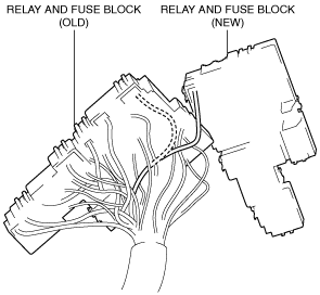
RELAY AND FUSE BLOCK REMOVAL/INSTALLATION
id092100498600
Removal
1. Disconnect the negative battery cable. (See NEGATIVE BATTERY CABLE DISCONNECTION/CONNECTION [SKYACTIV-G 2.0, SKYACTIV-G 2.5 (WITHOUT i-stop)].) (See NEGATIVE BATTERY CABLE DISCONNECTION/CONNECTION [SKYACTIV-G 2.0, SKYACTIV-G 2.5].) (See NEGATIVE BATTERY CABLE DISCONNECTION/CONNECTION [SKYACTIV-D 2.2].)
2. Remove the air cleaner assembly. (See INTAKE-AIR SYSTEM REMOVAL/INSTALLATION [SKYACTIV-G 2.0, SKYACTIV-G 2.5].) (See INTAKE-AIR SYSTEM REMOVAL/INSTALLATION [SKYACTIV-D 2.2].)
3. Remove the battery and the battery tray. (See BATTERY REMOVAL/INSTALLATION [SKYACTIV-G 2.0, SKYACTIV-G 2.5].) (See BATTERY REMOVAL/INSTALLATION [SKYACTIV-D 2.2].)
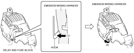
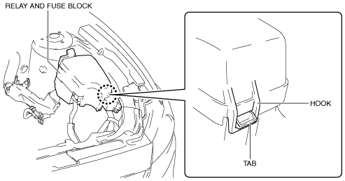
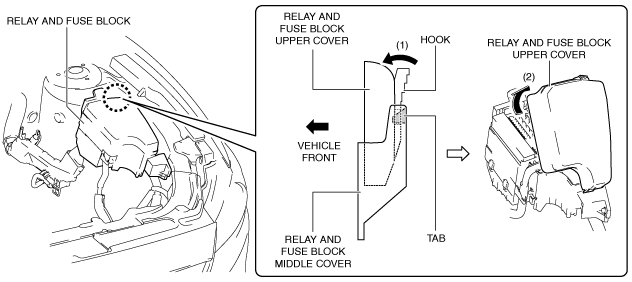
4. While pressing the relay and fuse block upper cover hook in the direction of the arrow (1) shown in the figure, lift up the relay and fuse block upper cover in the direction of the arrow (2) to detach the relay and fuse block upper cover hook from the relay and fuse block middle cover tab.
am6zzw00012888
|
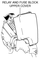
5. Remove the relay and fuse block upper cover.
6. Remove all the relays and fuses.
7. Remove the front body control module (FBCM). (See FRONT BODY CONTROL MODULE (FBCM) REMOVAL/INSTALLATION.)
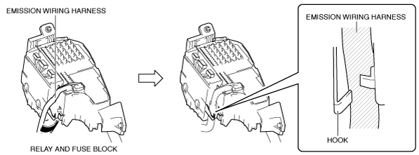
8. While pressing the relay and fuse block hook in the direction of the arrow (1) shown in the figure, set the emission wiring harness away in the direction of the arrow (2) shown in the figure from the relay and fuse block hook.
am6zzw00012889
|
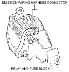
9. Disconnect the emission wiring harness connectors.
am6zzw00008244
|
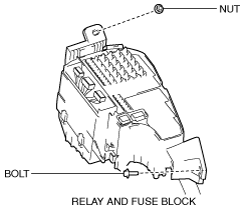
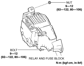
10. Remove the nut and bolt.
am6zzw00012890
|
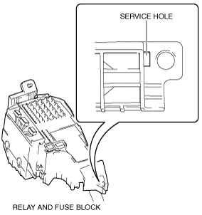
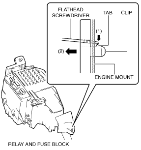
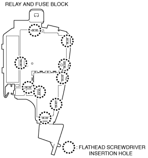
11. Insert a tape-wrapped flathead screwdriver into the service hole in the position shown in the figure.
am6zzw00008246
|
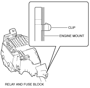
12. While pressing the clip tab of the relay and fuse block in the direction of the arrow (1) shown in the figure, pull the clip of the relay and fuse block in the direction of the arrow (2) to detach the clip tab of the relay and fuse block from the engine mount.
am6zzw00012891
|
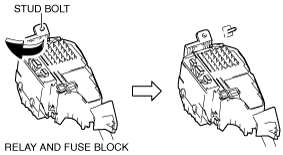
13. Pull out the relay and fuse block clip.
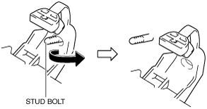
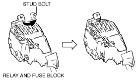
14. Pull out the relay and fuse block from the stud bolt and set it aside as shown in the figure.
am6zzw00008248
|
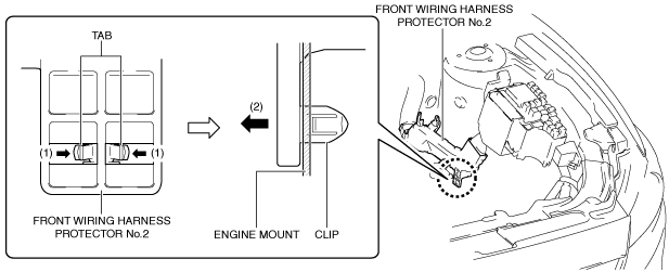
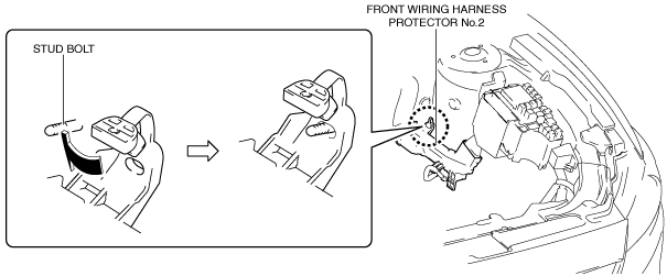
15. While pressing the clip tabs of front wiring harness protector No.2 in the direction of the arrows (1) shown in the figure, pull the clip of front wiring harness protector No.2 in the direction of the arrow (2) shown in the figure to detach the clip tabs of front wiring harness protector No.2 from the engine mount.
am6zzw00012892
|
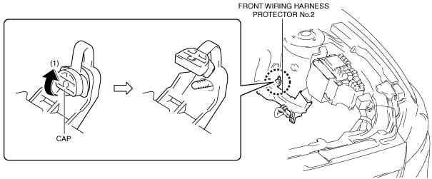
16. Pull out the front wiring harness protector No.2 clip.
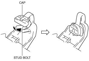
17. Lift up the front wiring harness protector No.2 cap in the direction of the arrow (1) shown in the figure.
am6zzw00012893
|
18. Pull out the front wiring harness protector No.2 from the stud bolt and set it aside as shown in the figure.
am6zzw00008251
|
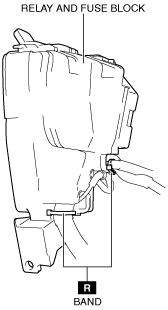
19. Cut the bands shown in the figure.
am6zzw00011241
|
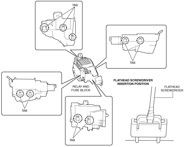
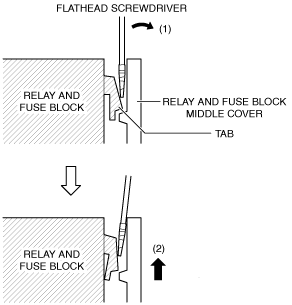
20. Insert a flathead screwdriver into the gap between the relay and fuse block middle cover tabs and the relay and fuse block lower cover as shown in the figure.
am6zzw00008253
|
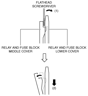
21. Move the flathead screwdriver in the direction of the arrow (1) shown in the figure, and pull down the relay and fuse block lower cover in the direction of the arrow (2) shown in the figure to detach the relay and fuse block middle cover tab from the relay and fuse block lower cover.
am6zzw00012894
|
22. Detach all the relay and fuse block middle cover tabs from the relay and fuse block lower cover, and remove the relay and fuse block lower cover from the relay and fuse block middle cover.
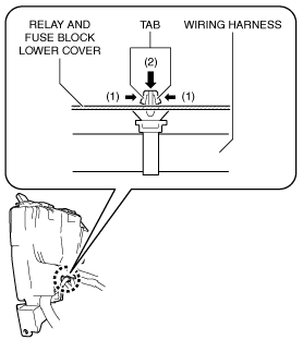
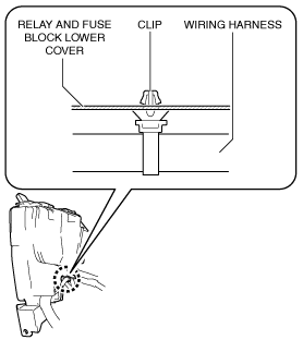
23. While pressing the wiring harness clip tabs in the direction of the arrows (1) shown in the figure, push out the wiring harness clip in the direction of the arrow (2) shown in the figure to detach the wiring harness clip tabs from the relay and fuse block lower cover.
am6zzw00012895
|
24. Pull out the wiring harness clip.
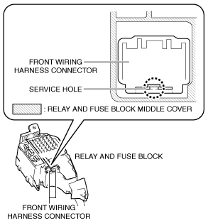
25. Insert a flathead screwdriver into the service hole in the position shown in the figure.
am6zzw00008256
|
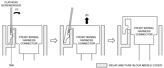
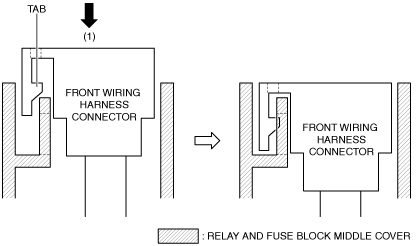
26. Move the flathead screwdriver in the direction of the arrow (1) shown in the figure, and lift up the front wiring harness connector in the direction of the arrow (2) shown in the figure to detach the front wiring harness connector tab from the relay and fuse block middle cover.
am6zzw00012896
|
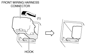
27. Move the front wiring harness connector in the direction of the arrow (1) shown in the figure, release the hook, and pull it out from the relay and fuse block middle cover.
am6zzw00012897
|
28. Pull out all the front wiring harness connectors from the relay and fuse block middle cover.
29. Insert the flathead screwdriver into the gap between the relay and fuse block middle cover and the relay and fuse block shown in the figure.
am6zzw00008259
|
30. Move the flathead screwdriver in the direction of the arrow (1) shown in the figure, and pull up the relay and fuse block middle cover in the direction of the arrow (2) shown in the figure to detach the relay and fuse block tab from the relay and fuse block middle cover.
am6zzw00012898
|
31. Detach all the relay and fuse block tabs from the relay and fuse block middle cover, and remove the relay and fuse block middle cover.
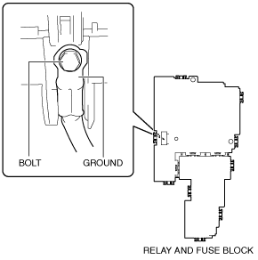
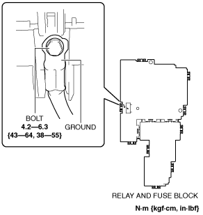
32. Remove the bolt.
am6zzw00008261
|
33. Remove the ground.
34. Set the removed relay and fuse block aside so that it does not scratch the vehicle and parts.
Installation
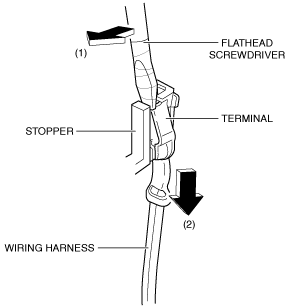
1. Move the flathead screwdriver in the direction of the arrow (1) shown in the figure, and pull the wiring harness in the direction of the arrow (2) while pressing the stopper to detach the relay or fuse terminal from the stopper.
am6zzw00008262
|
2. Relocate all relay and fuse terminals to the new relay and fuse block.
am6zzw00008263
|
3. Install the ground.
am6zzw00010146
|
4. Install the bolt.
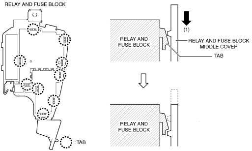
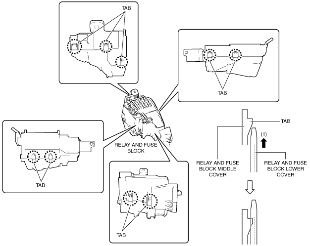
5. Move the relay and fuse block middle cover in the direction of arrow (1) shown in the figure and insert the relay and fuse block tab into the relay and fuse block middle cover.
am6zzw00012899
|
6. Insert all the relay and fuse block tabs into the relay and fuse block middle cover and install the relay and fuse block middle cover.
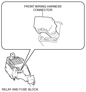
7. Insert the front wiring harness connector into the relay and fuse block middle cover.
am6zzw00010148
|
8. Move the front wiring harness connector in the direction of arrow (1) shown in the figure to engage the front wiring harness connector tab with the relay and fuse block middle cover.
am6zzw00012900
|
9. Install all the front wiring harness connectors to the relay and fuse block middle cover.
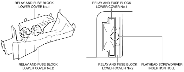
10. Insert a flathead screwdriver into the gap between relay and fuse block lower covers No.1 and 2 shown in the figure.
am6zzw00012901
|
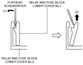
11. Move the flathead screwdriver in the direction of the arrow (1) shown in the figure, and pull up relay and fuse block lower cover No.1 in the direction of the arrow (2) shown in the figure to detach the relay and fuse block lower cover No.1 tab from relay and fuse block lower cover No.2.
am6zzw00012902
|
12. Detach all the relay and fuse block lower cover No.1 tabs from relay and fuse block lower cover No.2, and disassemble the relay and fuse block lower cover.
13. Move the relay and fuse block lower cover in the direction of arrow (1) shown in the figure and insert the relay and fuse block middle cover tab into the relay and fuse block lower cover.
am6zzw00012903
|
14. Insert all the relay and fuse block middle cover tabs into the relay and fuse block lower cover and install the relay and fuse block lower cover.
15. Install the wiring harness clip to the relay and fuse block lower cover.
am6zzw00011243
|
16. Install the bands shown in the figure.
am6zzw00011241
|
17. Insert the front wiring harness protector No.2 into the stud bolt.
am6zzw00012904
|
18. Insert the front wiring harness protector No.2 cap into the stud bolt.
am6zzw00011245
|
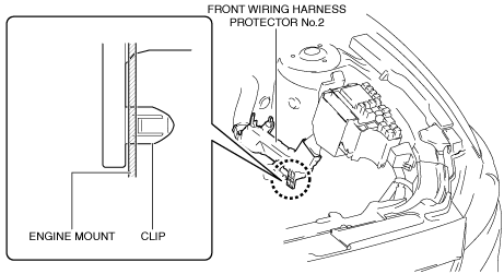
19. Install the front wiring harness protector No.2 clip to the engine mount.
am6zzw00012905
|
20. Insert the relay and fuse block into the stud bolt.
am6zzw00011247
|
21. Insert the relay and fuse block clip into the engine mount.
am6zzw00011248
|
22. Install the nut and bolt.
am6zzw00012906
|
23. Connect the emission wiring harness connectors.
am6zzw00008244
|
24. Press the emission wiring harness into the relay and fuse block hook.
am6zzw00011250
|
25. Install the front body control module (FBCM). (See FRONT BODY CONTROL MODULE (FBCM) REMOVAL/INSTALLATION.)
26. Install all the relays and fuses.
27. Engage the relay and fuse block upper cover hook with the relay and fuse block middle cover tab.
am6zzw00011251
|
28. Install the relay and fuse block upper cover.
am6zzw00012907
|
29. Install the parts removed in Steps 2 and 3 in “REMOVAL”. (See Removal.)
30. Perform the "Verify Relay and Fuse Block Replacement". (See Verify Relay and Fuse Block Replacement.)
31. Connect the negative battery cable. (See NEGATIVE BATTERY CABLE DISCONNECTION/CONNECTION [SKYACTIV-G 2.0, SKYACTIV-G 2.5 (WITHOUT i-stop)].) (See NEGATIVE BATTERY CABLE DISCONNECTION/CONNECTION [SKYACTIV-G 2.0, SKYACTIV-G 2.5].) (See NEGATIVE BATTERY CABLE DISCONNECTION/CONNECTION [SKYACTIV-D 2.2].)
Verify Relay and Fuse Block Replacement
1. Temporarily connect the negative battery cable to verify that the related wiring harness is not heated.
2. Switch the ignition ON (engine off).
3. Verify that the fuse is not burnt out and the related wiring harness is not heated.
4. Perform the initial settings for the following systems:
5. Verify DTCs using the M-MDS.
6. If there is no malfunction in Step 1, 3, and 5, start the engine and maintain the idle status.
7. Operate all the switches of the interior/exterior lights of the vehicle and verify that all the light bulbs illuminate and flash.
8. Operate the audio, climate control, wiper switch, and selector lever (ATX) and verify that they operate correctly.
9. Shift the selector lever to the P position, race the engine at approx. 3,000 rpm from engine idling, and verify that there is no malfunction. (ATX)
10. Perform a road test and verify that low speed, acceleration, shift-up, and shift-down conditions are normal. (ATX)