 |
am3zzw00019678
PARKING SENSOR SWITCH INSPECTION
id092200042700
Continuity Inspection
1. Disconnect the negative battery cable. (See NEGATIVE BATTERY CABLE DISCONNECTION/CONNECTION [SKYACTIV-D 2.2].)(See NEGATIVE BATTERY CABLE DISCONNECTION/CONNECTION [SKYACTIV-G 2.0, SKYACTIV-G 2.5].)(See NEGATIVE BATTERY CABLE DISCONNECTION/CONNECTION [SKYACTIV-G 2.0, SKYACTIV-G 2.5 (WITHOUT i-stop)].)
2. Remove the following parts:
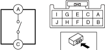
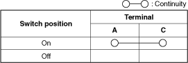
3. Verify that the continuity between the cluster switch terminals is as indicated in the table.
am3zzw00019678
|
am3zzw00019679
|
LED Illumination Inspection
1. Disconnect the negative battery cable. (See NEGATIVE BATTERY CABLE DISCONNECTION/CONNECTION [SKYACTIV-D 2.2].)(See NEGATIVE BATTERY CABLE DISCONNECTION/CONNECTION [SKYACTIV-G 2.0, SKYACTIV-G 2.5].)(See NEGATIVE BATTERY CABLE DISCONNECTION/CONNECTION [SKYACTIV-G 2.0, SKYACTIV-G 2.5 (WITHOUT i-stop)].)
2. Remove the following parts:
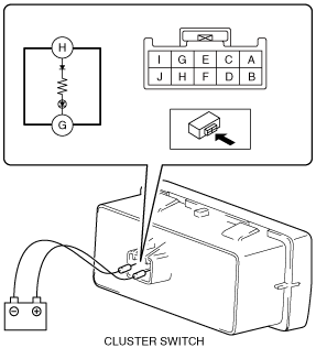
3. Apply battery voltage to cluster switch terminal F, and connect terminal G to ground.
4. Verify that the LED is turned on.
am3zzw00019680
|