 |
ac5wzw00000886
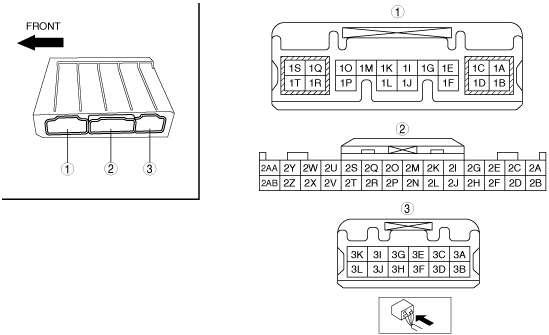
FRONT BODY CONTROL MODULE (FBCM) INSPECTION
id094000002100
1. Remove the fuse box cover. (See RELAY AND FUSE BLOCK REMOVAL/INSTALLATION.)
2. Remove the front body control module (FBCM) from the fuse box. (See FRONT BODY CONTROL MODULE (FBCM) REMOVAL/INSTALLATION.)
3. Verify that the voltages of each of the terminals are as indicated in the Terminal Voltage Table (Reference).
Terminal Voltage Table (Reference)
ac5wzw00000886
|
|
Terminal |
Signal |
Connected to |
Measurement conditions |
Voltage (V) |
Inspection item(s) |
|
|---|---|---|---|---|---|---|
|
1A
|
Power supply
|
HAZARD 25 A fuse
|
Under any condition
|
B+
|
• HAZARD 25 A fuse
• Related wiring harness
|
|
|
1B
|
Power supply
|
HAZARD 25 A fuse
|
Under any condition
|
B+
|
• HAZARD 25 A fuse
• Related wiring harness
|
|
|
1C
|
Ignition power supply
|
• Climate control unit
• Water pump (with water pump)
• Front seat warmer control unit
• Rear seat warmer control unit
• A/C relay
• PTC heater*1
|
Ignition switched ON (engine off)
|
B+
|
• Climate control unit
• Water pump (with water pump)
• Front seat warmer control unit
• Rear seat warmer control unit
• A/C relay
• PTC heater*1
• Related wiring harness
|
|
|
Ignition switched OFF (LOCK)
|
1.0 or less
|
|||||
|
1D
|
Signal ground
|
Body ground
|
Under any condition
|
1.0 or less
|
• Related wiring harness
|
|
|
1E
|
Rear turn light (RH) control
|
Rear turn light (RH)
|
Ignition switched ON (engine off)
|
Turn switch at right turn light position
|
1.0 or less Û B+
|
• Rear turn light (RH)
• Related wiring harness
|
|
Turn switch is in position other than above
|
1.0 or less
|
|||||
|
1F
|
Side turn light (RH) control
|
Side turn light (RH)
|
Ignition switched ON (engine off)
|
Turn switch at right turn light position
|
1.0 or less Û B+
|
• Side turn light (RH)
• Related wiring harness
|
|
Turn switch is in position other than above
|
1.0 or less
|
|||||
|
1G
|
Front turn light (RH) control
|
Front turn light (RH)
|
Ignition switched ON (engine off)
|
Turn switch at right turn light position
|
1.0 or less Û B+
|
• Front turn light (RH)
• Related wiring harness
|
|
Turn switch is in position other than above
|
1.0 or less
|
|||||
|
1H
|
—
|
—
|
—
|
—
|
—
|
|
|
1I
|
License light control
|
• Taillight (LH, RH)
• License plate light (LH, RH)
|
Light switch at TNS position
|
B+
|
• Taillight (LH, RH)
• License plate light (LH, RH)
• Related wiring harness
|
|
|
Light switch at OFF position
|
1.0 or less
|
|||||
|
1J
|
Parking light control
|
• Parking light (LH, RH)
• Signature wing illumination (LH, RH)*2
|
Light switch at TNS position
|
B+
|
• Parking light (LH, RH)
• Signature wing illumination (LH, RH)*2
• Related wiring harness
|
|
|
Light switch at OFF position
|
1.0 or less
|
|||||
|
1K
|
—
|
—
|
—
|
—
|
—
|
|
|
1L
|
Horn relay control
|
Horn relay
|
Horn switch not pressed
|
B+
|
• Horn relay
• Related wiring harness
|
|
|
Horn switch pressed
|
1.0 or less
|
|||||
|
1M
|
Headlight relay (LO) control
|
Headlight LO relay
|
Light switch at HEAD position
|
1.0 or less
|
• Headlight LO relay
• Related wiring harness
|
|
|
Light switch is in position other than above
|
B+
|
|||||
|
1N
|
—
|
—
|
—
|
—
|
—
|
|
|
1O*3
|
Theft-deterrent horn input signal
|
Rear body control module (RBCM)
|
M-MDS is connected and theft-deterrent is sounded using data monitor function
|
1.0 or less
|
• Rear body control module (RBCM)
• Related wiring harness
|
|
|
M-MDS is connected and theft-deterrent is not sounded using data monitor function
|
B+
|
|||||
|
1P
|
Rear window defogger relay control
|
Rear window defogger relay
|
Ignition switched ON (engine off)
|
Rear window defogger switch OFF
|
B+
|
• Rear window defogger relay
• Related wiring harness
|
|
Rear window defogger switch ON
|
1.0 or less
|
|||||
|
1Q*4
|
Headlight cleaner motor control
|
Headlight cleaner motor
|
Ignition switched ON (engine off) and light switch at HEAD position
|
Turn front washer switch ON 2 times within 2 s
|
B+→ 1.0 or less
|
• Headlight cleaner motor
• Related wiring harness
|
|
No operation
|
1.0 or less
|
|||||
|
1R*3
|
Theft-deterrent horn power supply
|
R.WIPER 15 A fuse
|
Under any condition
|
B+
|
• R.WIPER 15 A fuse
• Related wiring harness
|
|
|
1S*4
|
Headlight cleaner power supply
|
H/CLEAN 20 A fuse
|
Under any condition
|
B+
|
• H/CLEAN 20 A fuse
• Related wiring harness
|
|
|
1T*3
|
Theft-deterrent horn output signal
|
Theft-deterrent horn
|
M-MDS is connected and theft-deterrent is sounded using data monitor function
|
B+
|
• Theft-deterrent horn
• Related wiring harness
|
|
|
M-MDS is connected and theft-deterrent is not sounded using data monitor function
|
1.0 or less
|
|||||
|
2A
|
Interior light power supply
|
ROOM 15 A fuse
|
Under any condition
|
B+
|
• ROOM 15 A fuse
• Related wiring harness
|
|
|
2B
|
Front turn light (LH) control
|
Front turn light (LH)
|
Ignition switched ON (engine off)
|
Turn switch at left turn light position
|
1.0 or less Û B+
|
• Front turn light (LH)
• Related wiring harness
|
|
Turn switch is in position other than above
|
1.0 or less
|
|||||
|
2C
|
Running light control
|
Front combination light (LH, RH)
|
Ignition switched ON (engine off) and light switch OFF
|
Running light illuminates
|
B+
|
• Front combination light (LH, RH)
• Related wiring harness
|
|
Running light turns off
|
1.0 or less
|
|||||
|
2D
|
Rear turn light (LH) control
|
Rear turn light (LH)
|
Ignition switched ON (engine off)
|
Turn switch at left turn light position
|
1.0 or less Û B+
|
• Rear turn light (LH)
• Related wiring harness
|
|
Turn switch is in position other than above
|
1.0 or less
|
|||||
|
2E
|
LIN communication
|
Current sensor
|
Terminal used for communication therefore determination based on terminal voltage is not possible.
|
|||
|
2F
|
Side turn light (LH) control
|
Side turn light (LH)
|
Ignition switched ON (engine off)
|
Turn switch at left turn light position
|
1.0 or less Û B+
|
• Side turn light (LH)
• Related wiring harness
|
|
Turn switch is in position other than above
|
1.0 or less
|
|||||
|
2G*6
|
LIN communication
|
Auto-light sensor/rain sensor
|
Terminal used for communication therefore determination based on terminal voltage is not possible.
|
|||
|
2H
|
LIN communication
|
DC-DC converter
|
Terminal used for communication therefore determination based on terminal voltage is not possible.
|
|||
|
2I
|
CAN_L
|
CAN system related module
|
Terminal used for communication therefore determination based on terminal voltage is not possible.
|
|||
|
2J
|
—
|
—
|
—
|
—
|
—
|
|
|
2K
|
CAN_H
|
CAN system related module
|
Terminal used for communication therefore determination based on terminal voltage is not possible.
|
|||
|
2L
|
CAN_L
|
CAN system related module
|
Terminal used for communication therefore determination based on terminal voltage is not possible.
|
|||
|
2M
|
Ignition power supply
|
C/U IG1 15 A fuse
|
Ignition switched ON (engine off)
|
B+
|
• C/U IG1 15 A fuse
• Related wiring harness
|
|
|
Ignition switched OFF (LOCK)
|
1.0 or less
|
|||||
|
2N
|
CAN_L
|
CAN system related module
|
Terminal used for communication therefore determination based on terminal voltage is not possible.
|
|||
|
2O
|
—
|
—
|
—
|
—
|
—
|
|
|
2P
|
CAN_H
|
CAN system related module
|
Terminal used for communication therefore determination based on terminal voltage is not possible.
|
|||
|
2Q
|
Brake fluid level switch signal
|
Brake fluid level sensor
|
Ignition switched ON (engine off)
|
Brake fluid level is less than MIN (brake fluid level sensor ON)
|
1.0 or less
|
• Brake fluid level sensor
• Related wiring harness
|
|
Brake fluid level is MIN or more (brake fluid level sensor OFF)
|
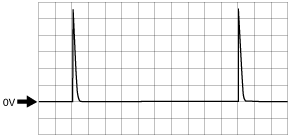
Wave pattern (See Pattern 1.)
|
|||||
|
2R
|
CAN_H
|
CAN system related module
|
Terminal used for communication therefore determination based on terminal voltage is not possible.
|
|||
|
2S*5
|
Washer level switch signal
|
Washer fluid-level sensor
|
Ignition switched ON (engine off)
|
Washer level is less than MIN (washer fluid-level sensor ON)
|
1.0 or less
|
• Washer fluid-level sensor
• Related wiring harness
|
|
Washer level is MIN or more (washer fluid-level sensor OFF)
|
Wave pattern (See Pattern 1.)
|
|||||
|
2T*1
|
PTC heater signal
|
PTC heater
|
Terminal used for communication therefore determination based on terminal voltage is not possible.
|
|||
|
2U
|
Ignition power supply
|
Start stop unit
|
Ignition switched ON (engine off)
|
B+
|
• Start stop unit
• Related wiring harness
|
|
|
Ignition switched OFF (LOCK)
|
1.0 or less
|
|||||
|
2V
|
—
|
—
|
—
|
—
|
—
|
|
|
2W
|
Headlight (LO) switch signal
|
Start stop unit
|
Light switch at HEAD position
|
1.0 or less
|
• Start stop unit
• Related wiring harness
|
|
|
Light switch at OFF position
|
B+
|
|||||
|
2X
|
Headlight relay (HI) control
|
Headlight HI relay
|
Headlight at HEAD position and dimmer switch at LO position
|
B+
|
• Headlight HI relay
• Related wiring harness
|
|
|
Headlight at HEAD position and dimmer switch at HIGH or passing position
|
1.0 or less
|
|||||
|
2Y
|
Windshield wiper (LO) switch signal
|
Start stop unit
|
Windshield wiper switch at ON position
|
1.0 or less
|
• Start stop unit
• Related wiring harness
|
|
|
Windshield wiper switch at OFF position
|
B+
|
|||||
|
2Z
|
Blower motor relay control
|
Blower relay
|
Ignition switched ON (engine off)
|
1.0 or less
|
• Blower relay
• Related wiring harness
|
|
|
Ignition switched OFF (LOCK)
|
B+
|
|||||
|
2AA
|
Autostop switch signal
|
Windshield wiper motor
|
Ignition switched ON (engine off)
|
Wipers are stopped in position other than park
|
B+
|
• Windshield wiper motor
• Related wiring harness
|
|
Wipers are stopped in park position
|
1.0 or less
|
|||||
|
2AB*7
|
Front fog light relay control
|
Front fog light relay
|
Light switch at HEAD position
|
Front fog light switch OFF
|
B+
|
• Front fog light relay
• Related wiring harness
|
|
Front fog light switch ON
|
1.0 or less
|
|||||
|
3A
|
Wiper power supply
|
WIPER 20 A fuse
|
Under any condition
|
B+
|
• WIPER 20 A fuse
• Related wiring harness
|
|
|
3B
|
Wiper power supply
|
WIPER 20 A fuse
|
Under any condition
|
B+
|
• WIPER 20 A fuse
• Related wiring harness
|
|
|
3C
|
Windshield wiper motor (HI) control
|
Windshield wiper motor
|
Ignition switched ON (engine off)
|
Windshield wiper switch at HI position
|
B+
|
• Windshield wiper motor
• Related wiring harness
|
|
Windshield wiper switch at OFF position
|
1.0 or less
|
|||||
|
3D
|
Power ground
|
Body ground
|
Under any condition
|
1.0 or less
|
• Related wiring harness
|
|
|
3E
|
Windshield wiper motor (HI) control
|
Windshield wiper motor
|
Ignition switched ON (engine off)
|
Windshield wiper switch at HI position
|
B+
|
• Windshield wiper motor
• Related wiring harness
|
|
Windshield wiper switch at OFF position
|
1.0 or less
|
|||||
|
3F
|
Windshield washer motor control
|
Washer motor
|
Ignition switched ON (engine off)
|
Windshield washer switch ON
|
B+
|
• Washer motor
• Related wiring harness
|
|
Windshield washer switch OFF
|
1.0 or less
|
|||||
|
3G
|
Windshield wiper motor (LOW) control
|
Windshield wiper motor
|
Ignition switched ON (engine off)
|
Windshield wiper switch at LOW position
|
B+
|
• Windshield wiper motor
• Related wiring harness
|
|
Windshield wiper switch at OFF position
|
1.0 or less
|
|||||
|
3H
|
Rear window washer motor control
|
Washer motor
|
Ignition switched ON (engine off)
|
Rear window washer switch ON
|
B+
|
• Washer motor
• Related wiring harness
|
|
Rear washer switch OFF
|
1.0 or less
|
|||||
|
3I
|
Windshield wiper motor (LOW) control
|
Windshield wiper motor
|
Ignition switched ON (engine off)
|
Windshield wiper switch at LOW position
|
B+
|
• Windshield wiper motor
• Related wiring harness
|
|
Windshield wiper switch at OFF position
|
1.0 or less
|
|||||
|
3J
|
Interior illumination power supply
|
• CD player*8
• DVD/CD player*9
• Shift pane;
• Drive selection switch
• Audio unit*10
• Commander switch*11
• Hazard warning switch
• Glove comparment light
• Electric parking brake
• Cluster switch
• Steering switch
• Cruise control switch
|
Light switch at TNS position
|
B+
|
• CD player*8
• DVD/CD player*9
• Shift pane;
• Drive selection switch
• Audio unit*10
• Commander switch*11
• Hazard warning switch
• Glove comparment light
• Electric parking brake
• Cluster switch
• Steering switch
• Cruise control switch
• Related wiring harness
|
|
|
Light switch at OFF position
|
—*12
|
|||||
|
3K
|
Power supply
|
HAZARD 25 A fuse
|
Under any condition
|
B+
|
• HAZARD 25 A fuse
• Related wiring harness
|
|
|
3L
|
Power supply
|
HAZARD 25 A fuse
|
Under any condition
|
B+
|
• HAZARD 25 A fuse
• Related wiring harness
|
|
Inspection Using an Oscilloscope (Reference)
Pattern 1
ac5jjw00000385
|