 |
am6zzw00015276
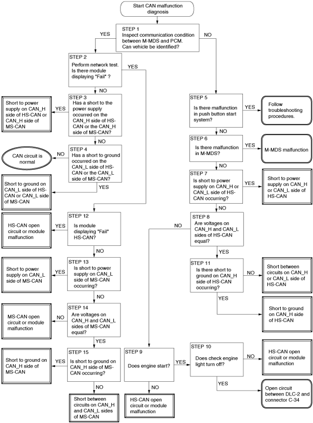
CONTROLLER AREA NETWORK (CAN) MALFUNCTION DIAGNOSIS FLOW [SKYACTIV-G 2.0/2.5, SKYACTIV-D 2.2 (MTX) (L.H.D.)]
id100238000100
CAN malfunction diagnosis flow
Flowchart
am6zzw00015276
|
Diagnostic procedure
|
Step |
Inspection |
Action |
|
|---|---|---|---|
|
1
|
INSPECT IF COMMUNICATION BETWEEN M-MDS AND PCM IS POSSIBLE
• Connect the M-MDS to the DLC-2.
• Switch the ignition ON (engine off).
• Perform vehicle identification.
• Can the vehicle be identified?
|
Yes
|
Go to the next step.
|
|
No
|
Go to Step 5 as a malfunction in the HS-CAN circuit has occurred.
|
||
|
2
|
INSPECT MODULE FOR INABILITY TO COMMUNICATE DUE TO CAN MALFUNCTION
• Implement the network test using the M-MDS.
• Is there a module indicating a malfunction?
|
Yes
|
Go to Step 12 as a malfunction in the CAN circuit has occurred.
|
|
No
|
Go to the next step.
|
||
|
3
|
INSPECT FOR SHORT TO POWER SUPPLY IN CAN_H SIDE OF MS-CAN OR HS-CAN
• Measure the voltage between the following terminals:
• Is B+ voltage measured between any of the terminals?
|
Yes
|
A short to power supply in the CAN_H side of MS-CAN or HS-CAN.
Determine the location of the short to power supply according to the diagnosis procedure for determining the location of a short to power supply.
|
|
No
|
Go to the next step.
|
||
|
4
|
INSPECT FOR SHORT TO GROUND IN CAN_L SIDE OF HS-CAN OR MS-CAN
• Measure the voltage between the following terminals:
• Is the voltage measured as 0 V?
|
Yes
|
A short to ground on the CAN_L side of the HS-CAN or MS-CAN has occurred.
Determine the location of the short to ground according to the diagnosis procedure for determining the location of a short to ground.
|
|
No
|
The current CAN circuit is normal, return to FOREWARD, and go to the next step of the CAN malfunction diagnosis in the troubleshooting procedure.
|
||
|
5
|
VERIFY IF PUSH BUTTON START SYSTEM HAS MALFUNCTION
• Switch the ignition ON (engine off).
• Can the ignition be switched ON?
|
Yes
|
Go to the next step.
|
|
No
|
A malfunction in the push button start system has occurred.
Perform diagnosis according to the symptom troubleshooting.
|
||
|
6
|
INSPECT FOR MALFUNCTION IN M-MDS
• Connect the M-MDS to a normal vehicle and implement vehicle identification.
• Can the vehicle be identified?
|
Yes
|
Go to the next step.
|
|
No
|
A malfunction in the M-MDS can be considered.
Repair the M-MDS.
|
||
|
7
|
INSPECT HS-CAN FOR SHORT TO POWER SUPPLY
• Measure the voltage between the following terminals:
• Is B+ voltage measured between any of the terminals?
|
Yes
|
A short to power supply in the CAN_H side or CAN_L of HS-CAN has occurred.
Determine the location of the short to power supply according to the diagnosis procedure for determining the location of a short to power supply.
|
|
No
|
Go to the next step.
|
||
|
8
|
INSPECT HS-CAN FOR OPEN CIRCUIT
• Measure the voltage between the following terminals:
• Is the voltage between both terminals (CAN_H side and CAN_L side) equal?
|
Yes
|
Go to Step 11 as a short to ground or a short between circuits has occurred in the HS-CAN.
|
|
No
|
Go to the next step.
|
||
|
9
|
DETERMINE IF OPEN CIRCUIT LOCATION IN HS-CAN CIRCUIT IS BETWEEN DLC AND CONNECTOR C-34 OR ELSEWHERE
• Start the engine to verify that the immobilizer system operates normally.
• Can the engine be started?
|
Yes
|
Go to the next step.
|
|
No
|
An open circuit has occurred between the PCM and connector C-34 in the HS-CAN.
Determine the location of the open circuit according to the diagnosis procedure for determining the location of an open circuit.
|
||
|
10
|
DETERMINE IF OPEN CIRCUIT LOCATION IN HS-CAN CIRCUIT IS BETWEEN DLC AND CONNECTOR C-34 OR ELSEWHERE
• Switch the ignition ON (engine off).
• Verify if the check engine light in the instrument cluster illuminates.
• Start the engine.
• Verify if the check engine light turns off.
• Does the check engine light turn off?
|
Yes
|
An open circuit between DLC-2 and connector C-34 has occurred.
Repair or replace the wiring harness for an open circuit, then return to Step 1.
|
|
No
|
An open circuit has occurred between the PCM and connector C-34 in the HS-CAN.
Determine the location of the open circuit according to the diagnosis procedure for determining the location of an open circuit.
|
||
|
11
|
VERIFY MALFUNCTION OCCURRED IN HS-CAN CIRCUIT
• Measure the voltage between the following terminals:
• Is the voltage between both terminals (CAN_H side and CAN_L side) 0 V?
|
Yes
|
A short to ground in CAN_H side of HS-CAN has occurred.
Determine the location of the short to ground according to the diagnosis procedure for determining the location of a short to ground.
|
|
No
|
A short between circuits in the CAN_H side and the CAN_L side of HS-CAN has occurred.
Determine the location of the short between circuits according to the diagnosis procedure for determining the location of a short between circuits.
|
||
|
12
|
DETERMINE CAN COMMUNICATION SPECIFICATION IN WHICH MALFUNCTION OCCURS
• Refer to the CAN communication specification quick reference table and verify the CAN communication specification (HS-CAN or MS-CAN) that is connected to the module which is indicating a malfunction.
• Is the module that is indicating a malfunction HS-CAN?
|
Yes
|
An open circuit in the HS-CAN has occurred.
Determine the location of the open circuit according to the diagnosis procedure for determining the location of an open circuit.
|
|
No
|
Go to the next step.
|
||
|
13
|
INSPECT CAN_L SIDE OF MS-CAN FOR SHORT TO POWER SUPPLY
• Measure voltage between DLC-2 terminal K (CAN_L side) and body ground.
• Can B+ voltage be measured?
|
Yes
|
A short to power supply in the CAN_L side of the MS-CAN has occurred.
Determine the location of the short to power supply according to the diagnosis procedure for determining the location of a short to power supply.
|
|
No
|
Go to the next step.
|
||
|
14
|
INSPECT MS-CAN FOR OPEN CIRCUIT
• Measure the voltage between the following terminals:
• Is the voltage between both terminals (CAN_H side and CAN_L side) equal?
|
Yes
|
Go to the next step.
|
|
No
|
Open circuit in MS-CAN has occurred.
Determine the location of the open circuit according to the diagnosis procedure for determining the location of an open circuit.
|
||
|
15
|
VERIFY MALFUNCTION OCCURRED IN MS-CAN
• Measure the voltage between the following terminals:
• Is the voltage between both terminals (CAN_H side and CAN_L side) 0 V?
|
Yes
|
A short to ground in the CAN_H side of the MS-CAN has occurred.
Determine the location of the short to ground according to the diagnosis procedure for determining the location of a short to ground.
|
|
No
|
A short between circuits on the CAN_H side and CAN_L side of MS-CAN has occurred.
Determine the location of the short between circuits according to the diagnosis procedure for determining the location of a short between circuits.
|
||
CAN communication specification quick reference table
|
CAN communication related module (M-MDS display) |
CAN communication specification |
|
|---|---|---|
|
HS-CAN |
MS-CAN |
|
|
PCM
(PCM)
|
×
|
|
|
DSC HU/CM
(ABS)
|
×
|
|
|
Radar unit
(SBS/MRCC)
|
×
|
|
|
TCM
(TCM)
|
×
|
|
|
Front body control module (FBCM)
(F_BCM)
|
×
|
|
|
Adaptive front lighting system (AFS) control module / auto leveling control module
(AFS)
|
×
|
|
|
DC-DC converter (i-ELOOP)
(DCDC)
|
×
|
|
|
4WD control module
(4×4)
|
×
|
|
|
Electric parking brake control module
(EPB)
|
×
|
|
|
Position memory control module
(DSM)
|
×
|
|
|
Audio amplifier
(AM)
|
×
|
|
|
Forward sensing camera (FSC)
(FSC)
|
×
|
|
|
EPS control module
(EPS)
|
×
|
|
|
MAZDA ERA-GLONASS control module
(DCM)
|
×
|
|
|
Start stop unit
(SSU)
|
×
|
|
|
Connectivity master unit (CMU)
(CMU)
|
×
|
|
|
SAS control module
(RCM)
|
×
|
|
|
Instrument cluster
(IC)
|
×
|
|
|
Climate control unit
(EATC)
|
|
×
|
|
Parking assist unit
(PSM)
|
|
×
|
|
Blind spot monitoring (BSM) control module (LH)
(BSML)
|
|
×
|
|
Rear mount camera
|
|
×
|
|
Rear body control module (RBCM)
(R_BCM)
|
|
×
|
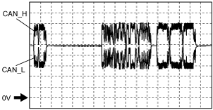
HS-CAN signal waveform
|
CAN circuit condition |
Signal waveform (reference) |
|---|---|
|
Normal
|
 |
|
• CAN_H
• CAN_L
|
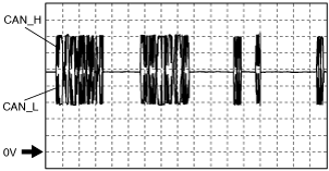
MS-CAN signal waveform
|
CAN circuit condition |
Signal waveform (reference) |
|---|---|
|
Normal
|
 |
|
• CAN_H
• CAN_L
|