DTC U3003:16 [ADAPTIVE LED HEADLIGHTS CONTROL MODULE]


id1502c1003300

System malfunction location

Adaptive LED headlights control module low power supply voltage input

Detection condition
•  Adaptive LED headlights control module power supply circuit voltage of 9 V or less is detected for 5 s or more with the ignition switched ON (engine off or on).
Fail-safe
•  When the setting is on using the personalization feature, the headlights HI turn on. (When setting is off using personalization feature, headlight HI illumination on/off depends on control by front body control module (FBCM))
•  The headlight leveling actuator is stopped at the position when the malfunction is determined.
Possible cause
•  DTCs are stored in the PCM.
•  Battery malfunction
•  Generator malfunction
•  Adaptive LED headlights control module connector or terminal malfunction
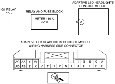
•  Adaptive LED headlights control module power supply circuit malfunction
―  Short to ground in wiring harness between METER1 10 A fuse and adaptive LED headlights control module terminal A
―  METER1 10 A fuse malfunction
―  Open circuit in wiring harness between IG1 relay and adaptive LED headlights control module terminal A
•  Adaptive LED headlights control module malfunction

Diagnostic Procedure

Step

Inspection

Action

1
VERIFY PCM DTCs
•  Perform the DTC inspection for the PCM using the M-MDS.
•  Is the DTC displayed?
Yes
Repair the malfunctioning part according to the applicable DTC troubleshooting.
No
Go to the next step.
2
INSPECT BATTERY
•  Is the battery normal?
Yes
Go to the next step.
No
Recharge or replace the battery, then go to Step 6.
3
INSPECT GENERATOR
•  Is the generator normal?
Yes
Go to the next step.
No
Replace the generator, then go to Step 6.
4
INSPECT ADAPTIVE LED HEADLIGHTS CONTROL MODULE CONNECTOR CONDITION
•  Switch the ignition to off.
•  Disconnect the adaptive LED headlights control module connector.
•  Inspect the connector engagement and connection condition and inspect the terminals for damage, deformation, corrosion, or disconnection.
•  Is the connector normal?
Yes
Go to the next step.
No
Repair or replace the connector, then go to Step 6.
5
VERIFY ADAPTIVE LED HEADLIGHTS CONTROL MODULE POWER SUPPLY VOLTAGE
•  Reconnect all the disconnected connectors.
•  Display PID VPWR_IG using the M-MDS.
•  Is the voltage B+?
Yes
Go to the next step.
No
Inspect the METER1 10 A fuse.
•  If a fuse is burnt out:
―  Repair or replace the wiring harness which is shorted to ground.
―  Replace the fuse.
•  If a fuse is damaged:
―  Replace the fuse.
•  If the fuse is normal:
―  Repair or replace the wiring harness which has an open circuit.
Go to the next step.
6
VERIFY THAT REPAIRS HAVE BEEN COMPLETED
•  Reconnect all the disconnected connectors.
•  Clear the adaptive LED headlights control module DTCs using the M-MDS.
•  Switch the ignition ON (engine off or on) and wait for 5 s or more.
•  Perform the DTC inspection for the adaptive LED headlights control module using the M-MDS.
•  Is DTC U3003:16 displayed?
Yes
Repeat the inspection from Step 1.
•  If the malfunction recurs, replace the adaptive LED headlights control module, then go to the next step.
No
Go to the next step.
7
VERIFY IF OTHER DTCs DISPLAYED
•  Are any other DTCs displayed?
Yes
Repair the malfunctioning part according to the applicable DTC troubleshooting.
No
DTC troubleshooting completed.