MAZDA RADAR CRUISE CONTROL (MRCC) SYSTEM
id151000002000
Outline
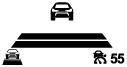
• The Mazda radar cruise control (MRCC) system can perform headway control and maintain a constant speed at a set vehicle speed and distance from a vehicle ahead using a radar unit which detects the vehicle ahead without the driver having to depress the accelerator or brake pedal. Additionally, if the detecting vehicle approaches the vehicle ahead too closely such as when the vehicle ahead is braking suddenly, the system alerts the driver using a warning sound and warning indication.
-
Warning
-
• Do not rely completely on the MRCC system and always drive carefully. There are limitations to the distance between the vehicles which can be controlled by the MRCC system, and if the accelerator pedal or brake pedal is mistakenly operated it could result in an accident. Always verify the safety of the surrounding area and depress the brake pedal while keeping a safe distance from the vehicle ahead.
• The MRCC system does not completely stop the vehicle using the automatic braking operation. Additionally, brake control is performed, however, there are limitations to the deceleration, and the system may be unable to decelerate sufficiently to avoid hitting the vehicle ahead if the vehicle ahead applies the brakes suddenly or another vehicle cuts into the driving lane, which could result in an accident. Always verify the safety of the surrounding area and depress the brake pedal while keeping a safe distance from the vehicle ahead.
Functions
• The MRCC system is equipped with the following indicated modes.
-
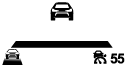
― Constant speed control mode: Drives the vehicle at the set vehicle speed set by the driver based on the cruise control switch operation signal.
― Headway control mode: When a vehicle ahead is detected while the vehicle is traveling in constant speed control mode, headway control with the vehicle ahead is performed while maintaining the set vehicle speed set by the driver and a constant distance between the vehicles.
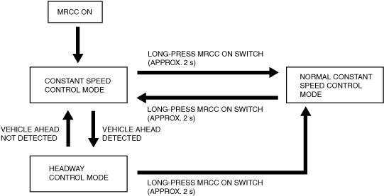
Mode switching function
-
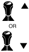
• The modes in the Mazda Radar Cruise Control (MRCC) system can be switched as follows.
-
Note
-
• When switching from constant speed control mode/headway control mode to normal constant speed control mode, the set vehicle speed must be reset. In addition, when switching from normal constant speed control mode to constant speed control mode/headway control mode, the vehicle speed becomes the speed set before switching from normal constant speed control mode.
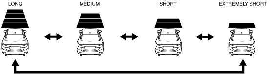
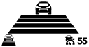
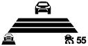
Distance between vehicles setting function
-
• Using the DISTANCE switch on the cruise control switch, the distance between vehicles can be controlled at 4 levels, including long→medium→short→extremely short. (Initial setting is set to LONG)
-
Caution
-
• The distances between vehicles indicated below are average values during travel on flat roads and differ depending on the driving and road conditions.
Distance between vehicles table (reference)
|
Set distance between vehicles
|
Detecting vehicle speed
|
|
30 km/h {19 mph}
|
40 km/h {25 mph}
|
50 km/h {31 mph}
|
60 km/h {37 mph}
|
70 km/h {43 mph}
|
80 km/h {50 mph}
|
90 km/h {56 mph}
|
100 km/h {62 mph}
|
110 km/h {68 mph}
|
|
Long
|
23 m
{75 ft}
|
29 m
{95 ft}
|
36 m
{118 ft}
|
42 m
{138 ft}
|
48 m
{157 ft}
|
55 m
{180 ft}
|
61 m
{200 ft}
|
67 m
{220 ft}
|
74 m
{243 ft}
|
|
Medium
|
19 m
{62 ft}
|
24 m
{79 ft}
|
29 m
{95 ft}
|
34 m
{112 ft}
|
39 m
{128 ft}
|
44 m
{144 ft}
|
49 m
{161 ft}
|
53 m
{174 ft}
|
58 m
{190 ft}
|
|
Short
|
15 m
{49 ft}
|
18 m
{59 ft}
|
22 m
{72 ft}
|
25 m
{82 ft}
|
29 m
{95 ft}
|
32 m
{105 ft}
|
36 m
{118 ft}
|
40 m
{131 ft}
|
43 m
{141 ft}
|
|
Extremely short
|
12 m
{39 ft}
|
14 m
{46 ft}
|
17 m
{56 ft}
|
20 m
{66 ft}
|
22 m
{72 ft}
|
25 m
{82 ft}
|
27 m
{89 ft}
|
30 m
{98 ft}
|
32 m
{105 ft}
|
|
Set distance between vehicles
|
Detecting vehicle speed
|
|
120 km/h {75 mph}
|
130 km/h {81 mph}
|
140 km/h {87 mph}
|
150 km/h {93 mph}
|
160 km/h {99 mph}
|
170 km/h {106 mph}
|
180 km/h {112 mph}
|
190 km/h {118 mph}
|
200 km/h {124 mph}
|
|
Long
|
80 m
{262 ft}
|
86 m
{282 ft}
|
93 m
{305 ft}
|
99 m
{325 ft}
|
105 m
{344 ft}
|
105 m
{344 ft}
|
105 m
{344 ft}
|
105 m
{344 ft}
|
105 m
{344 ft}
|
|
Medium
|
63 m
{207 ft}
|
68 m
{223 ft}
|
73 m
{240 ft}
|
78 m
{256 ft}
|
83 m
{272 ft}
|
88 m
{289 ft}
|
90 m
{295 ft}
|
90 m
{295 ft}
|
90 m
{295 ft}
|
|
Short
|
47 m
{154 ft}
|
50 m
{164 ft}
|
54 m
{177 ft}
|
57 m
{187 ft}
|
61 m
{200 ft}
|
64 m
{210 ft}
|
68 m
{223 ft}
|
72 m
{236 ft}
|
75 m
{246 ft}
|
|
Extremely short
|
35 m
{115 ft}
|
38 m
{125 ft}
|
40 m
{131 ft}
|
43 m
{141 ft}
|
45 m
{148 ft}
|
48 m
{157 ft}
|
51 m
{167 ft}
|
53 m
{174 ft}
|
56 m
{184 ft}
|
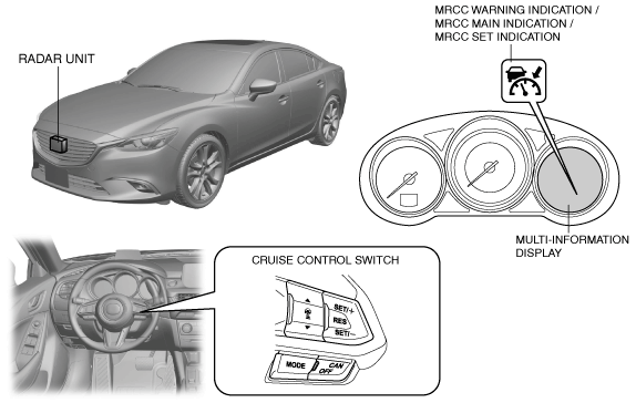
System conditions display function
-
• The radar unit displays the system status using the MRCC main indication/MRCC set indication/MRCC warning indication, active driving display/multi-information display, and center display.
|
Condition
|
MRCC main indication
|
MRCC set indication
|
MRCC warning indication
|
Multi-information display indication
|
Active driving display indication
|
Center display
|
|
MRCC system is OFF
|
Off
|
Off
|
Off
|
No display
|
No display
|
No display
|
|
MRCC system is ON
|
MRCC system is on standby
|
On
|
Off
|
Off
|
 |
No display
|
No display
|
|
Vehicle speed is set
|
Off
|
On
|
Off
|
 |
 |
No display
|
|
Vehicle ahead is detected
|
Off
|
On
|
Off
|
 |
 |
No display
|
|
Distance between vehicles
|
Long
|
Off
|
On
|
Off
|
|
 |
No display
|
|
Medium
|
Off
|
On
|
Off
|
 |
 |
No display
|
|
Short
|
Off
|
On
|
Off
|
 |
 |
No display
|
|
Extremely short
|
Off
|
On
|
Off
|
 |
 |
No display
|
|
Accelerator pedal is depressed
|
Off
|
On
|
Off
|
No display
|
No display
|
No display
|
|
Shift up/down required (MTX)
|
Off
|
Off
|
Off
|
 |
 |
No display
|
|
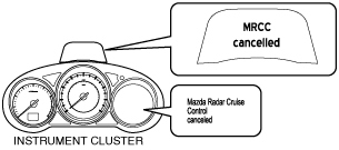
MRCC system is ON
|
Switching from constant speed control mode/headway control mode to normal constant speed control mode
|
Off
|
Off
|
Off
|
 |
No display
|
No display
|
|
Deceleration exceeding system limits required
|
Off
|
Off
|
Off
|
 |
 |
No display
|
|
MRCC system is automatically canceled due to low vehicle speed
|
On
|
Off
|
Off
|
|
 |
No display
|
|
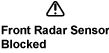
Dirty radar unit is detected
|
Off
|
Off
|
On
|
 |
No display
|
Warning display*1
|
|
Malfunction occurred in MRCC system
|
Off
|
Off
|
On
|
 |
No display
|
Warning display*1
|
Structural View
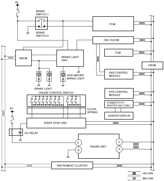
System Wiring Diagram
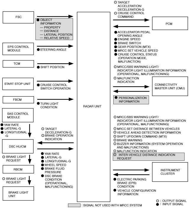
Block Diagram
Block diagram (MRCC/SBS/DRSS)
Operation
• When all of the following conditions are met, the MRCC system goes on operation standby.
Operation condition
-
― Selector lever is in D or M position
― Vehicle speed is within range of approx. 30—200 km/h {19—124 mph} (European (L.H.D. U.K.) specs.)
― Vehicle speed is within range of approx. 30—145 km/h {19—90 mph} (Australian, General (L.H.D.) specs.)
― MRCC system is ON
― DSC is ON
― Brake pedal is not depressed
― DSC is not operating
― TCS is not operating
― Smart city brake support (SCBS) is not operating
― Smart brake support (SBS) is not operating
― Electric parking brake is released
― No malfunction in DSC system (No DTCs stored in memory)
― No malfunction in MRCC system (No DTCs stored in memory)
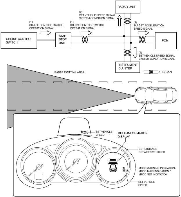
Constant speed control mode
-
1. The PCM recognizes the set vehicle speed set by the driver based on the cruise control switch operation signal sent from the start stop unit when the operation conditions are met.
2. When the PCM recognizes the set vehicle speed, it sends a set vehicle speed signal and system condition signal to the radar unit, instrument cluster.
3. The radar unit sends a target acceleration speed signal to the PCM based on the set vehicle speed signal and system condition signal.
4. The PCM performs engine control to maintain the set vehicle speed based on the signal from the radar unit.
5. The instrument cluster and active driving display display the system operation screen based on the sent vehicle speed signal and system condition signal from the PCM.
-
Note
-
• If the vehicle speed decreases to 20 km/h {12 mph} or less while in constant speed control mode, the radar unit cancels constant speed control mode and switches to standby status.
• When the radar unit detects the target information while in constant speed control mode, it switches the mode to headway control mode.
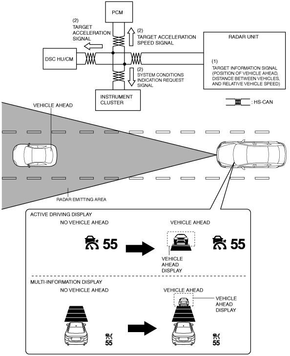
Headway control mode
-
1. When the radar unit detects the target information while the vehicle is traveling in constant speed control mode, it switches the mode to headway control mode.
2. The radar unit calculates the target acceleration speed based on the following, and sends the target acceleration speed signal to the PCM and DSC HU/CM. Additionally, it sends the system conditions indication request signal to the instrument cluster.
-
― Distance between vehicles set by driver
― Target information
― Detecting vehicle speed
3. The PCM performs engine control to maintain distance between vehicles based on the signal from the radar unit.
4. The DSC HU/CM controls braking to maintain distance between vehicles based on the signal from the radar unit.
5. The instrument cluster the vehicle ahead screen based on the signal from the radar unit.
-
Note
-
• In the following cases, the system transitions from headway control mode to constant speed mode.
-
― Vehicle ahead accelerates over set vehicle speed of detecting vehicle
― Vehicle ahead or detecting vehicle switches driving lanes, and vehicle ahead of detecting vehicle no longer exists
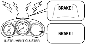
Inter-vehicle distance limit warning
-
• If any of the following conditions is met, the warning alarm in the instrument cluster is activated and the brake warning in the display is indicated to urge the driver to take action such as braking.
-
― Radar unit determines that crash is unavoidable even if automatic braking is performed at maximum possible deceleration rate
― Vehicle ahead performs emergency braking
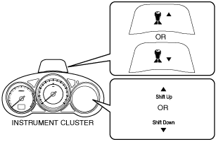
Shift up/shift down request (MTX)
-
• If the transaxle gear position is not appropriate to the vehicle speed while the MRCC system is operating, a shift up/shift down request is displayed in the active driving display of the instrument cluster.
-
Caution
-
• If the vehicle continues to be driven without following the shift up request, the continuous high engine speed will apply a load on the engine which could cause engine damage. Shift the gears up in accordance with the shift up request.
• If the vehicle continues to be driven without following the shift down request, it could cause the engine to stall. Shift the gears down in accordance with the shift down request.
-
• If the vehicle continues to be driven without following the shift up/shift down request, the radar unit will automatically cancel the MRCC system to reduce the load on the engine.
-
Note
-
• When driving on a steep downhill, a shift down request may be indicated to decrease the load on the brakes required to maintain a constant vehicle speed.