-
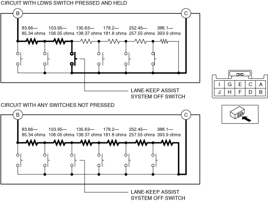
• Resistance with lane-keep assist system OFF switch pressed and held
-
― 187.61—191.39 ohms
-
-
• Resistance with any switches not pressed
-
― 1,139.99—1,163.01 ohms
-
am3zzw00019685
|
LANE-KEEP ASSIST SYSTEM OFF SWITCH INSPECTION
id152000008900
Resistance Inspection
1. Disconnect the negative battery cable. (See NEGATIVE BATTERY CABLE DISCONNECTION/CONNECTION [SKYACTIV-D 2.2].)(See NEGATIVE BATTERY CABLE DISCONNECTION/CONNECTION [SKYACTIV-G 2.0, SKYACTIV-G 2.5].)(See NEGATIVE BATTERY CABLE DISCONNECTION/CONNECTION [SKYACTIV-G 2.0, SKYACTIV-G 2.5 (WITHOUT i-stop)].)
2. Remove the following parts:
3. Measure the resistance between cluster switch terminals B and C under the following conditions:
am3zzw00019685
|
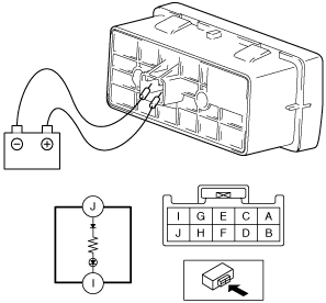
LED Illumination Inspection
1. Disconnect the negative battery cable. (See NEGATIVE BATTERY CABLE DISCONNECTION/CONNECTION [SKYACTIV-D 2.2].)(See NEGATIVE BATTERY CABLE DISCONNECTION/CONNECTION [SKYACTIV-G 2.0, SKYACTIV-G 2.5].)(See NEGATIVE BATTERY CABLE DISCONNECTION/CONNECTION [SKYACTIV-G 2.0, SKYACTIV-G 2.5 (WITHOUT i-stop)].)
2. Remove the following parts:
3. Apply battery positive voltage to cluster switch terminal J, and connect terminal I to ground.
am3uuw00010057
|
4. Verify that the LED illuminates.