 |
ac5wzw00000990
REAR STABILIZER REMOVAL/INSTALLATION [4WD]
id0214008005a2
1. Switch the ignition ON (engine off).
2. Release the electric parking brake.
3. Switch the ignition off.
4. Disconnect the negative battery cable. (See NEGATIVE BATTERY CABLE DISCONNECTION/CONNECTION [SKYACTIV-G 2.0, SKYACTIV-G 2.5].) (See NEGATIVE BATTERY CABLE DISCONNECTION/CONNECTION [SKYACTIV-G 2.0, SKYACTIV-G 2.5 (WITHOUT i-stop)].) (See NEGATIVE BATTERY CABLE DISCONNECTION/CONNECTION [SKYACTIV-D 2.2].)
5. Remove the wheels and tires. (WHEEL AND TIRE REMOVAL/INSTALLATION.)
6. Disconnect the auto leveling sensor link. (See AUTO LEVELING SENSOR REMOVAL/INSTALLATION.)
ac5wzw00000990
|
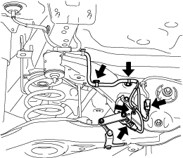
7. Disconnect the wiring harness clips and connectors installed to the rear crossmember.
am6zzw00014698
|
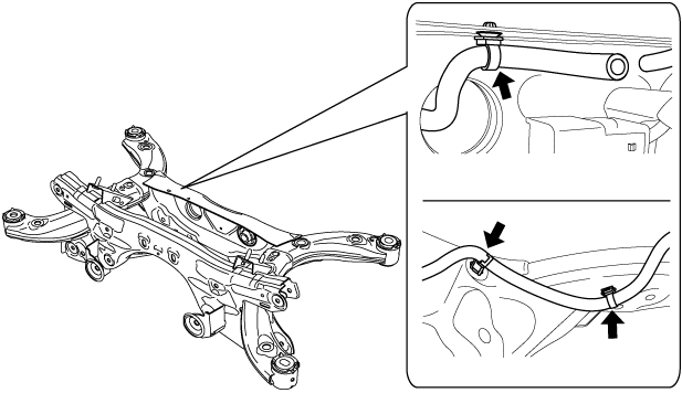
8. Set the rear differential breather hose aside.
am6zzw00012933
|
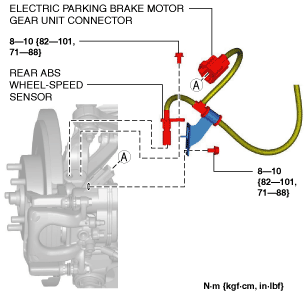
9. Disconnect the rear ABS wheel-speed sensor wiring harness and the electric parking brake motor gear unit connector and set it aside so that it does not interfere with the servicing. (See REAR ABS WHEEL-SPEED SENSOR REMOVAL/INSTALLATION [4WD].)
am6zzw00012937
|
10. Remove the middle pipe. (See EXHAUST SYSTEM REMOVAL/INSTALLATION [SKYACTIV-D 2.2].)
11. Remove the propeller shaft. (See PROPELLER SHAFT REMOVAL/INSTALLATION.)
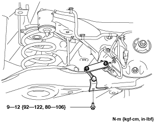
12. Remove the rear coil spring. (See REAR COIL SPRING REMOVAL/INSTALLATION.)
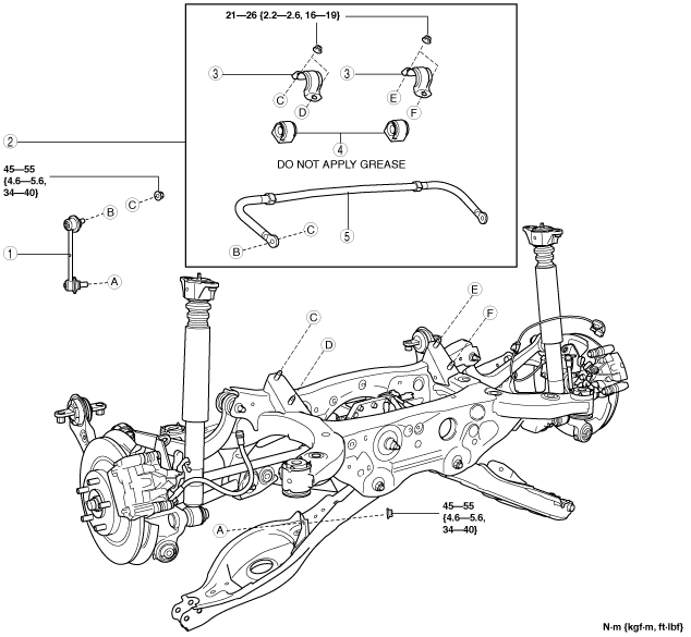
13. Remove in the order indicated in the table.
14. Install in the reverse order of removal. (See Suspension Links Installation Note.)
15. Inspect the wheel alignment and adjust it if necessary. (See REAR WHEEL ALIGNMENT.)
16. Perform the headlight auto leveling system initial setting. (See HEADLIGHT AUTO LEVELING SYSTEM INITIALIZATION.)
ac5wzw00007144
|
|
1
|
Rear stabilizer control link
|
|
2
|
Rear stabilizer component
|
|
3
|
Rear stabilizer bracket
|
|
4
|
Rear stabilizer bushing
|
|
5
|
Rear stabilizer
|
Rear Stabilizer Component Removal Note
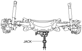
1. Support the rear crossmember component with a jack and remove the rear crossmember installation nuts.
ac5uuw00000188
|
2. Press down on the rear crossmember component until the rear stabilizer component can be removed from the vehicle using a jack.
ac5wzw00002321
|
Suspension Links Installation Note
1. When installing the joint sections with rubber bushings, perform the following procedures.
Rear Stabilizer Bracket Removal Note
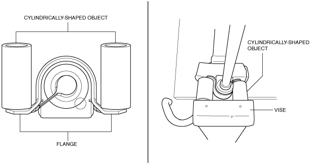
1. Secure the rear stabilizer bracket flange using a vise.
ac5uuw00000922
|
Rear Stabilizer Bushing, Rear Stabilizer Bracket Installation Note
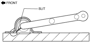
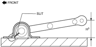
1. Install the rear stabilizer bushing with the slit pointing toward the front of the vehicle.
ac5wzw00002732
|
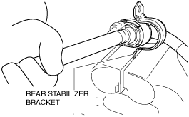
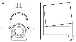
2. Install the rear stabilizer bracket to the front stabilizer bushing by hand using the following procedure.
3. If the rear stabilizer bracket cannot be installed by hand, install it using a vise.
ac5wzw00002163
|
4. During rear stabilizer bracket installation, keep the deviation in the positions of the rear stabilizer bracket and the rear stabilizer bushing within the range shown in the figure.
ac5wzw00002426
|
5. After installing the rear stabilizer bracket, verify that the positions of the rear stabilizer bracket and the rear stabilizer bushing are within the range shown in the figure.
ac5uuw00000926
|
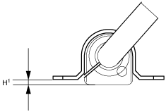
6. After installing the rear stabilizer bracket, verify that the right and left-side positions of the rear stabilizer bracket are within the range shown in the figure.
ac5wzw00002145
|
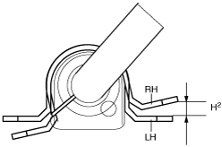
7. Place the rear stabilizer component on a level workbench, and verify that it is within the range shown in the figure.
ac5wzw00002733
|
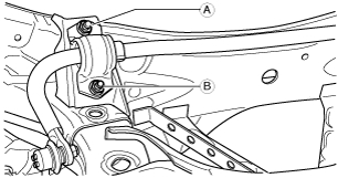
Rear Stabilizer Component Installation Note
1. Temporarily tighten bolts A and B shown in the figure.
ac5uuw00000169
|
2. Tighten bolt A.
3. Tighten bolt B.
4. Tighten bolt A.
5. Lift up the rear crossmember component using a jack and install the rear crossmember installation nuts.
ac5uuw00000188
|