 |
am6zzw00014701
WHEEL HUB COMPONENT REMOVAL/INSTALLATION [2WD]
id0312008004a1
1. Switch the ignition ON (engine off).
2. Release the electric parking brake.
3. Switch the ignition off.
4. Disconnect the negative battery cable. (See NEGATIVE BATTERY CABLE DISCONNECTION/CONNECTION [SKYACTIV-G 2.0, SKYACTIV-G 2.5].) (See NEGATIVE BATTERY CABLE DISCONNECTION/CONNECTION [SKYACTIV-G 2.0, SKYACTIV-G 2.5 (WITHOUT i-stop)].) (See NEGATIVE BATTERY CABLE DISCONNECTION/CONNECTION [SKYACTIV-D 2.2].)
5. Remove the wheel and tire. (See WHEEL AND TIRE REMOVAL/INSTALLATION.)
6. When working on the left side of the vehicle, disconnect the auto leveling sensor link. (With headlight auto leveling system) (See AUTO LEVELING SENSOR REMOVAL/INSTALLATION.)
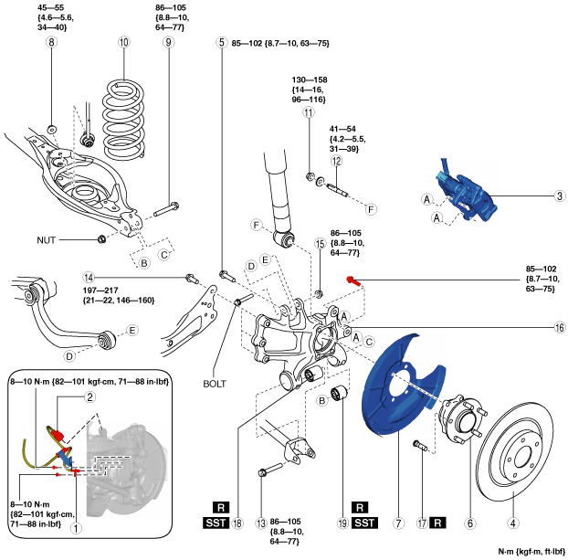
7. Remove in the order indicated in the table.
8. Install in the reverse order of removal. (See Suspension Links Installation Note.)
9. When the hub support, hub support bushing (front), or hub support bushing (rear) is replaced, inspect the wheel alignment and adjust it if necessary. (See REAR WHEEL ALIGNMENT.)
10. When the auto leveling sensor link is disconnected, perform the headlight auto leveling system initial setting. (See HEADLIGHT AUTO LEVELING SYSTEM INITIALIZATION.)
am6zzw00014701
|
|
1
|
Rear ABS wheel-speed sensor
|
|
2
|
Electric parking brake motor gear unit connector
|
|
3
|
Brake caliper component
|
|
4
|
Disc plate
|
|
5
|
Bolt (wheel hub)
|
|
6
|
Wheel hub
|
|
7
|
Dust cover
|
|
8
|
Rear stabilizer control link lower side nut
|
|
9
|
Rear lower arm outer bolt
|
|
10
|
Rear coil spring
|
|
11
|
Rear shock absorber lower nut
|
|
12
|
Stud bolt
|
|
13
|
Rear lateral link outer bolt
|
|
14
|
Rear trailing link installation bolt
|
|
15
|
Nut (rear upper arm outer side)
|
|
16
|
Hub support
|
|
17
|
Wheel hub bolt
(See Wheel Hub Bolt Removal Note.)
(See Wheel Hub Bolt Removal Note.)
|
|
18
|
Hub support bushing (front)
|
|
19
|
Hub support bushing (rear)
|
Brake Caliper Component Removal Note
1. Remove the brake caliper component from the hub support and suspend it out of the way using a cable.
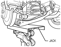
Rear Lower Arm Outer Bolt Removal Note
1. Support the rear lower arm using a jack.
ac5wzw00002562
|
2. Remove the rear lower arm outer bolt.
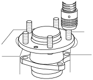
Wheel Hub Bolt Removal Note
1. Remove the wheel hub bolt using a press.
ac5wzw00002563
|
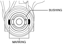
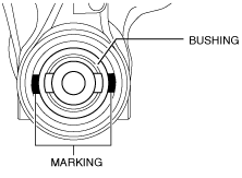
Hub Support Bushing (Front) Removal Note
1. Mark the hub support as shown in the figure.
ac5wzw00002564
|
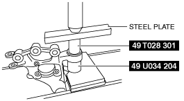
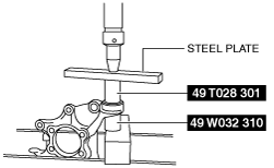
2. Press the rear hub support bushing (front) out using the SSTs.
ac5wzw00002565
|
Hub Support Bushing (Rear) Removal Note
1. Mark the hub support as shown in the figure.
ac5wzw00002566
|
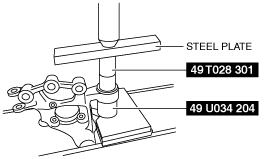
2. Press the rear hub support bushing (rear) out using the SSTs.
ac5wzw00002567
|
Suspension Links Installation Note
1. When installing the joint sections with rubber bushings, perform the following procedures.
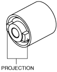
Hub Support Bushing (Rear) Installation Note
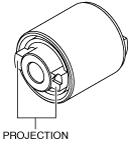
1. Align the projection of a hub support bushing with the marks placed during removal.
ac5wzw00002568
|
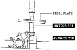
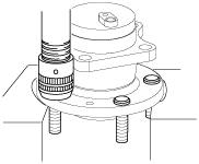
2. Install a new hub support bushing (rear) using the SSTs.
ac5wzw00002569
|
Hub Support Bushing (Front) Installation Note
1. Align the projection of a hub support bushing with the marks placed during removal.
ac5wzw00002570
|
2. Install a new hub support bushing (front) using the SSTs.
ac5wzw00002571
|
Wheel Hub Bolt Installation Note
1. Install the new wheel hub bolt using a press.
acxuuw00003087
|