|
1
|
INSPECT FUSE CONDITION
• Is the fuse (MAIN 200A, ABS/DSCM 50A) normal?
|
Yes
|
Go to the next step.
|
|
No
|
Replace the fuse, then go to Step 6.
|
|
2
|
VERIFY PUMP MOTOR OPERATION
• Using the M-MDS, perform the simulation inspection for pump motor.
• Does the pump motor operate?
|
Yes
|
Go to Step 6.
|
|
No
|
Go to the next step .
|
|
3
|
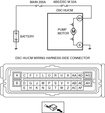
INSPECT MOTOR RELAY POWER SUPPLY FOR OPEN CIRCUIT
• Switch the ignition to off.
• Disconnect the DSC HU/CM connector.
• Inspect for continuity between DSC HU/CM terminal AH and the positive battery terminal.
• Is there continuity?
|
Yes
|
Go to the next step.
|
|
No
|
Refer to the wiring diagram and verify whether or not there is a common connector between DSC HU/CM terminal AH and the positive battery terminal.
If there is a common connector:
• Determine the malfunctioning part by inspecting the common connector and the terminal for corrosion, damage, or pin disconnection, and the common wiring harness for an open circuit.
• Repair or replace the malfunctioning part.
If there is no common connector:
• Repair or replace the wiring harness which has an open circuit.
Go to Step 6.
|
|
4
|
INSPECT MOTOR RELAY POWER SUPPLY FOR SHORT CIRCUIT
• Inspect for continuity between DSC HU/CM terminal AH and body ground.
• Is there continuity?
|
Yes
|
Refer to the wiring diagram and verify whether or not there is a common connector between DSC HU/CM terminal AH and the positive battery terminal.
If there is a common connector:
• Determine the malfunctioning part by inspecting the common connector and the terminal for corrosion, damage, or pin disconnection, and the common wiring harness for a short to ground.
• Repair or replace the malfunctioning part.
If there is no common connector:
• Repair or replace the wiring harness which has a short to ground.
Go to Step 6.
|
|
No
|
Go to the next step.
|
|
5
|
INSPECT PUMP MOTOR GROUND FOR OPEN CIRCUIT
• Inspect for continuity between DSC HU/CM terminal B and body ground.
• Is there continuity?
|
Yes
|
Go to the next step.
|
|
No
|
Repair or replace the wiring harness, then go to the next step.
|
|
6
|
VERIFY DTC TROUBLESHOOTING COMPLETED
• Using the M-MDS, clear the DTC from the DSC HU/CM.
• Start the engine and drive the vehicle at 6 km/h {4 mph} or more.
• Gradually slow down and stop vehicle.
• Using the M-MDS, perform the DSC HU/CM DTC inspection.
• Is the same DTC present?
|
Yes
|
Repeat the inspection from Step1.
If the malfunction recurs, replace the DSC HU/CM, then go to the next step.
|
|
No
|
Go to the next step.
|
|
7
|
VERIFY NO DTC IS PRESENT
• Are any DTCs present?
|
Yes
|
Go to the applicable DTC inspection.
|
|
No
|
DTC troubleshooting completed.
|