 |
am6zzw00014980
EPS CONTROL MODULE INSPECTION
id061300802400
1. Remove the driver-side front scuff plate. (See FRONT SCUFF PLATE REMOVAL/INSTALLATION.)
2. Remove the driver-side front side trim. (See FRONT SIDE TRIM REMOVAL/INSTALLATION.)
3. Remove the upper panel. (See UPPER PANEL REMOVAL/INSTALLATION.)
4. Remove the shift lever knob (MTX vehicles). (See MANUAL TRANSAXLE SHIFT MECHANISM REMOVAL/INSTALLATION [C66M-R].) (See MANUAL TRANSAXLE SHIFT MECHANISM REMOVAL/INSTALLATION [D66M-R, D66MX-R].)
5. Remove the selector lever knob (ATX vehicles). (See AUTOMATIC TRANSAXLE SHIFT MECHANISM REMOVAL/INSTALLATION.)
6. Remove the shift panel. (See SHIFT PANEL REMOVAL/INSTALLATION.)
7. Remove the rear console. (See REAR CONSOLE REMOVAL/INSTALLATION.)
8. Remove the front console box. (See FRONT CONSOLE BOX REMOVAL/INSTALLATION.)
9. Remove the side wall. (See SIDE WALL REMOVAL/INSTALLATION.)
10. Remove the front console. (See FRONT CONSOLE REMOVAL/INSTALLATION.)
11. Disconnect the bonnet release lever from the lower panel. (See BONNET LATCH AND RELEASE LEVER REMOVAL/INSTALLATION.)
12. Remove the fuel-filler lid opener lever. (See FUEL-FILLER LID OPENER AND LEVER REMOVAL/INSTALLATION.)
13. Remove the lower panel. (See LOWER PANEL REMOVAL/INSTALLATION.)
14. Remove the driver-side front heat duct. (See FRONT HEAT DUCT REMOVAL/INSTALLATION.)
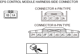
15. Attach the tester lead to the underside of the EPS CM connector and inspect the voltage according to the terminal voltage table (reference).
Terminal Voltage Table (Reference)
am6zzw00014980
|
|
Terminal |
Signal name |
Connected to |
Measured item |
Measured terminal (measurement condition) |
Voltage (V) |
Inspection item(s) |
|---|---|---|---|---|---|---|
|
1A
|
Ground
|
Ground point
|
Voltage
|
Under any condition
|
1 or less
|
• Wiring harness (1A—ground point)
|
|
1B
|
Battery power supply
|
Battery
|
Voltage
|
Under any condition
|
B+
|
• Wiring harness (1B—battery)
• Fuse (EPS 60A)
|
|
2B*1
2A*2
|
CAN_H
|
—
|
Perform DTC inspection
|
—
|
||
|
2B
|
—
|
—
|
—
|
—
|
—
|
—
|
|
2B
|
—
|
—
|
—
|
—
|
—
|
—
|
|
2C
|
—
|
—
|
—
|
—
|
—
|
—
|
|
2D
|
CAN_L
|
—
|
Perform DTC inspection
|
—
|
||
|
2E
|
—
|
—
|
—
|
—
|
—
|
—
|
|
2F
|
—
|
—
|
—
|
—
|
—
|
—
|
|
2G
|
—
|
—
|
—
|
—
|
—
|
—
|
|
2A*1
2H*2
|
Ignition power supply
|
IG1 relay
|
Voltage
|
Ignition ON (engine off or on)
|
B+
|
• Wiring harness (2A*1/2H*2—IG1 relay—battery)
• Fuse (SRS1 7.5A)
|
|
Ignition OFF (LOCK)
|
1 or less
|
|||||