 |
am6zzw00013685
ANTENNA FEEDER NO.3 INSPECTION
id092000813000
Without cennter display
1. Disconnect the negative battery cable. (See NEGATIVE BATTERY CABLE DISCONNECTION/CONNECTION [SKYACTIV-D 2.2].) (See NEGATIVE BATTERY CABLE DISCONNECTION/CONNECTION [SKYACTIV-G 2.0, SKYACTIV-G 2.5].) (See NEGATIVE BATTERY CABLE DISCONNECTION/CONNECTION [SKYACTIV-G 2.0, SKYACTIV-G 2.5 (WITHOUT i-stop)].)
2. Remove the following parts:
3. Remove the rear passenger's assist handle. (See ASSIST HANDLE REMOVAL/INSTALLATION.)
4. Partially peel back the headliner.
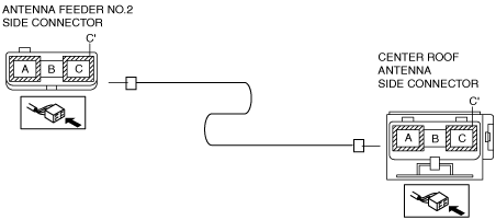
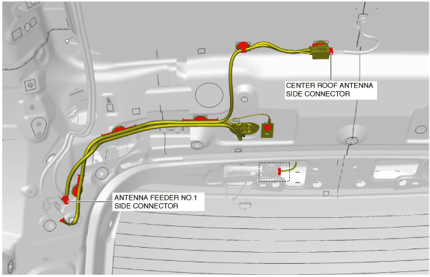
5. Disconnect antenna feeder No.1.
6. Disconnect the center roof antenna connector.
am6zzw00013685
|
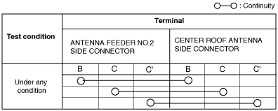
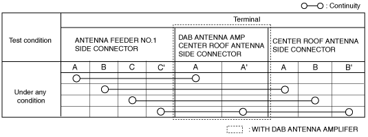
7. Verify that the continuity between antenna feeder No.3 terminals is as indicated in the table.
am6zzw00013664
|
am6zzw00013667
|
With center display
1. Disconnect the negative battery cable. (See NEGATIVE BATTERY CABLE DISCONNECTION/CONNECTION [SKYACTIV-D 2.2].) (See NEGATIVE BATTERY CABLE DISCONNECTION/CONNECTION [SKYACTIV-G 2.0, SKYACTIV-G 2.5].) (See NEGATIVE BATTERY CABLE DISCONNECTION/CONNECTION [SKYACTIV-G 2.0, SKYACTIV-G 2.5 (WITHOUT i-stop)].)
2. Remove the following parts:
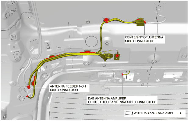
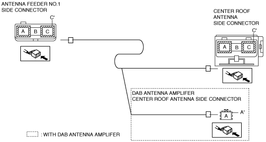
3. Disconnect antenna feeder No.3.
4. Disconnect the center roof antenna connector.
am6zzw00013668
|
5. Verify that the continuity between antenna feeder No.3 terminals is as indicated in the table.
am6zzw00013669
|
am6zzw00013663
|