 |
am6zzw00014865
ENGINE REMOVAL/INSTALLATION [SKYACTIV-D 2.2]
id0110s5800400
Operation After Replacing Timing Chain
1. After replacing the engine, perform the following procedure.
|
STEP |
ACTION |
PAGE/CONDITION |
|---|---|---|
|
1
|
Perform KOEO self-test procedure.
|
|
|
2
|
Switch the ignition off.
|
—
|
|
3
|
Verify that the check engine light does not illuminate.
|
—
|
|
4
|
Perform KOER self-test procedure.
|
|
|
5
|
Perform fuel injector injection amount correction.
|
|
|
6
|
Perform timing chain learning procedure.
|
|
|
7
|
Clear the DTCs.
|
|
|
8
|
Switch the ignition off.
|
—
|
1. Disconnect the negative battery cable. (See NEGATIVE BATTERY CABLE DISCONNECTION/CONNECTION [SKYACTIV-D 2.2].)
2. Remove the engine cover. (See ENGINE COVER REMOVAL/INSTALLATION [SKYACTIV-D 2.2].)
3. Remove the air cleaner and air hose as a single unit. (See INTAKE-AIR SYSTEM REMOVAL/INSTALLATION [SKYACTIV-D 2.2].)
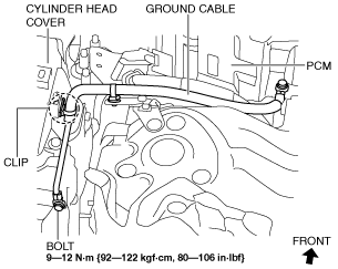
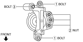
4. Remove the bolts, nut and connector shown in the figure, and set the wiring harness aside.
am6zzw00014865
|
5. Remove the battery and battery tray. (See BATTERY REMOVAL/INSTALLATION [SKYACTIV-D 2.2].)
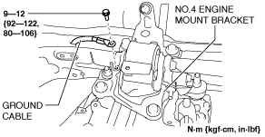
6. Disconnect the ground cable shown in the figure.
Right side
am6zzw00010081
|
Left side
am6zzw00010082
|
7. Remove the following parts as a single unit. (See INTAKE-AIR SYSTEM REMOVAL/INSTALLATION [SKYACTIV-D 2.2].):
8. Drain the engine coolant. (See ENGINE COOLANT REPLACEMENT [SKYACTIV-D 2.2].)
9. Drain the transaxle oil (MTX) or ATF (ATX). (See MANUAL TRANSAXLE OIL REPLACEMENT [D66M-R, D66MX-R].) (See AUTOMATIC TRANSAXLE FLUID (ATF) REPLACEMENT [GW6A-EL, GW6AX-EL].)
10. Disconnect the selector cable. (ATX) (See AUTOMATIC TRANSAXLE SHIFT MECHANISM REMOVAL/INSTALLATION.)
11. Disconnect the control cable. (MTX) (See MANUAL TRANSAXLE SHIFT MECHANISM REMOVAL/INSTALLATION [D66M-R, D66MX-R].)
12. Remove the clutch release cylinder with the pipe still connected. (MTX) (See CLUTCH RELEASE CYLINDER REMOVAL/INSTALLATION [D66M-R, D66MX-R].)
13. Disconnect the brake vacuum hose. (See VACUUM HOSE REMOVAL/INSTALLATION.)
14. Disconnect the fuel main hose and fuel return hose No.1. (See LOWER CASE REMOVAL/INSTALLATION [SKYACTIV-D 2.2].)
15. Disconnect the upper radiator hose and water hose (upper side of radiator).
16. Disconnect the heater hose. (See A/C UNIT REMOVAL/INSTALLATION.)
17. Remove the front wheels and tires. (See WHEEL AND TIRE REMOVAL/INSTALLATION.)
18. Remove the front under cover No.1 and No.2. (See FRONT UNDER COVER No.1 REMOVAL/INSTALLATION.) (See FRONT UNDER COVER No.2 REMOVAL/INSTALLATION.)
19. Remove the front splash shield No.1. (See SPLASH SHIELD REMOVAL/INSTALLATION.)
20. Disconnect the ATF oil hose from the radiator. (if equipped) (See OIL COOLER REMOVAL/INSTALLATION [GW6A-EL, GW6AX-EL].)
21. Disconnect the lower radiator hose. (See THERMOSTAT REMOVAL/INSTALLATION [SKYACTIV-D 2.2].)
22. Remove the charge air cooler outlet hose. (See INTAKE-AIR SYSTEM REMOVAL/INSTALLATION [SKYACTIV-D 2.2].)
23. Set the front mudguard (RH) aside. (See MUDGUARD REMOVAL/INSTALLATION.)
24. Remove the charge air cooler outlet pipe. (See CHARGE AIR COOLER REMOVAL/INSTALLATION [SKYACTIV-D 2.2].)
25. Remove the drive belt. (See DRIVE BELT REMOVAL/INSTALLATION [SKYACTIV-D 2.2].)
26. Remove the A/C compressor with the pipes connected and secure the A/C compressor using wire or rope so that it is out of the way. (See A/C COMPRESSOR REMOVAL/INSTALLATION.)
27. Remove the middle pipe installation nut (catalytic converter side) and secure the middle pipe using wire or rope so that it is out of the way. (2WD) (See EXHAUST SYSTEM REMOVAL/INSTALLATION [SKYACTIV-D 2.2].)
28. Remove the middle pipe. (4WD) (See EXHAUST SYSTEM REMOVAL/INSTALLATION [SKYACTIV-D 2.2].)
29. Remove the propeller shaft. (4WD) (See PROPELLER SHAFT REMOVAL/INSTALLATION.)
30. Disconnect the front drive shaft (LH) from the transaxle side and set it aside. (See FRONT DRIVE SHAFT REMOVAL/INSTALLATION.)
31. Disconnect the front drive shaft (RH) from the transaxle side and set it aside. (2WD) (See FRONT DRIVE SHAFT REMOVAL/INSTALLATION.)
32. Remove the drive shaft (RH). (4WD) (See FRONT DRIVE SHAFT REMOVAL/INSTALLATION.)
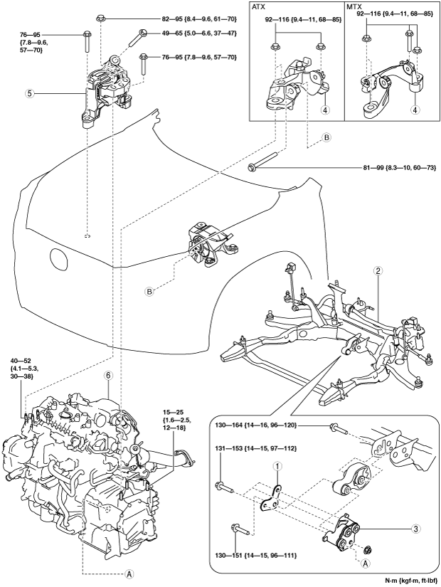
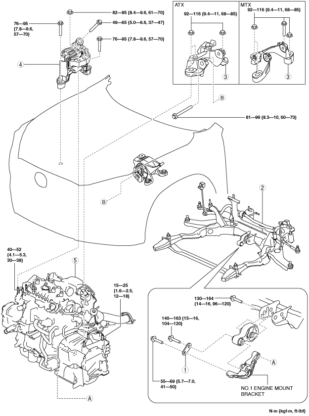
33. Remove in the order indicated in the table.
34. Install in the reverse order of removal.
35. Refill the transaxle oil (MTX) or ATF (ATX). (See MANUAL TRANSAXLE OIL REPLACEMENT [D66M-R, D66MX-R].) (See AUTOMATIC TRANSAXLE FLUID (ATF) REPLACEMENT [GW6A-EL, GW6AX-EL].)
36. Refill the engine coolant. (See ENGINE COOLANT REPLACEMENT [SKYACTIV-D 2.2].)
37. If the engine is replaced, perform “Operation After Replacing Timing Chain”. (See Operation After Replacing Timing Chain.)
38. Start the engine, and inspect and adjust the following:
2WD
am6zzw00012628
|
|
1
|
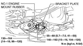
Bracket plate
|
|
2
|
No.1 engine mount rubber, front crossmember component
|
|
3
|
No.1 engine mount bracket
|
|
4
|
No.4 engine mount bracket
|
|
5
|
No.3 engine mount
|
|
6
|
Engine, transaxle
|
4WD
am6zzw00014040
|
|
1
|
Bracket plate
|
|
2
|
No.1 engine mount rubber, front crossmember component
|
|
3
|
No.4 engine mount bracket
|
|
4
|
No.3 engine mount
|
|
5
|
Engine, transaxle
|
No.1 Engine Mount Rubber, Front Crossmember Component Removal Note
1. Disconnect the service plug. (With i-ELOOP) (See SERVICE PLUG DISCONNECTION/CONNECTION [i-ELOOP].)
2. Disconnect the generator terminal B cable. (With i-ELOOP) (See GENERATOR REMOVAL/INSTALLATION [SKYACTIV-D 2.2 (WITH i-ELOOP)].)
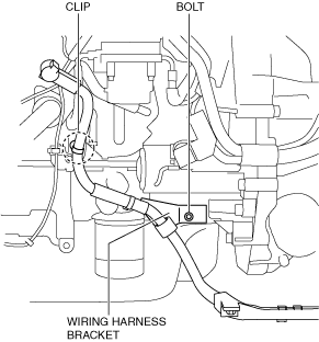
3. Remove the bolt shown in the figure. (With i-ELOOP)
am6zzw00014866
|
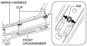
4. Remove the clips shown in the figure and set the wiring harness aside. (With i-ELOOP)
am6zzw00010084
|
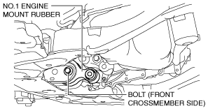
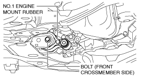
5. Loosen the No.1 engine mount rubber installation bolt (front crossmember side) shown in the figure.
2WD
ac5wzw00005635
|
4WD
am6zzw00014041
|
6. Remove the No.1 engine mount rubber and the front crossmember component as a single unit. (See FRONT CROSSMEMBER REMOVAL/INSTALLATION.)
No.3 Engine Mount, No.4 Engine Mount Bracket Removal Note
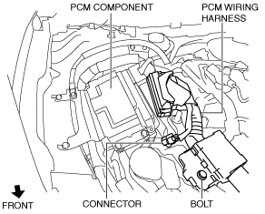
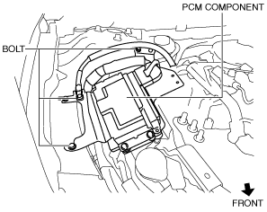
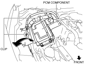
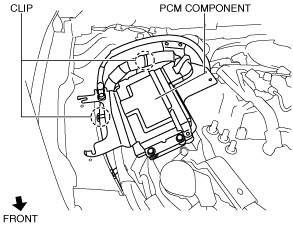
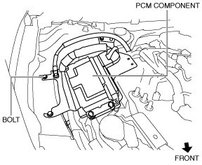
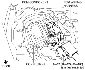
1. Set the PCM wiring harness and PCM component aside using the following procedure:
am6zzw00011364
|
am6zzw00010086
|
am6zzw00010087
|
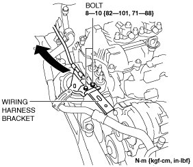
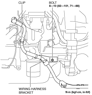
2. Set the wiring harness bracket aside using the following procedure:
am6zzw00011365
|
am6zzw00011366
|
3. Remove the seal plate installed to the underside of the oil pan. (See OIL PAN REMOVAL/INSTALLATION [SKYACTIV-D 2.2].)
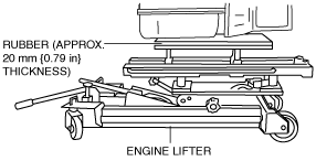
4. Secure the engine and transaxle using a commercially available engine lifter.
ac5wzw00005640
|
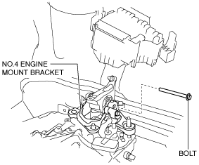
5. Remove the No.4 engine mount bracket.
6. Remove the No.3 engine mount.
Engine Mount Installation Note
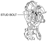
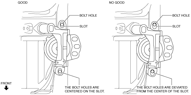
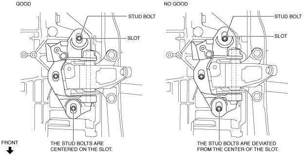
1. Tighten the engine front cover stud bolts.
ac5wzw00005641
|
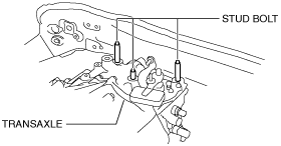
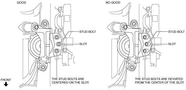
2. Tighten the transaxle stud bolts.
ac5wzw00005642
|
3. Secure the engine and transaxle using a commercially available engine lifter.
ac5wzw00005640
|
4. Temporarily tighten the No.3 engine mount installation bolts and nuts using the following procedure:
ac5wzw00005208
|
ac5wzw00005209
|
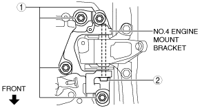
5. Temporarily tighten the No.4 engine mount bracket installation bolt and nuts using the following procedure:
ac5wzw00005643
|
MTX
ac5wzw00005210
|
ATX
ac5wzw00005211
|
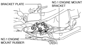
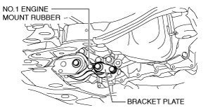
6. Install the No.1 engine mount rubber and the front crossmember component as a single unit. (See FRONT CROSSMEMBER REMOVAL/INSTALLATION.)
7. Temporarily tighten the following parts:
ac5wzw00005644
|
am6zzw00014042
|
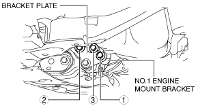
8. Tighten the No.1 engine mount bracket and bracket plate installation bolts in the order shown in the figure. (2WD)
ac5wzw00005646
|
9. Tighten the No.3 engine mount installation bolts and nuts in the order shown in the figure.
ac5wzw00005647
|
Tightening torque
|
Installation position |
Tightening torque |
|---|---|
|
1
|
76—95 N·m {7.8—9.6 kgf·m, 57—70 ft·lbf}
|
|
2
|
82—95 N·m {8.4—9.6 kgf·m, 61—70 ft·lbf}
|
|
3
|
49—65 N·m {5.0—6.6 kgf·m, 37—47 ft·lbf}
|
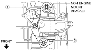
10. Tighten the No.4 engine mount bracket installation bolt and nuts in the order shown in the figure.
MTX
ac5wzw00005212
|
ATX
ac5wzw00005648
|
Tightening torque
|
Installation position |
Tightening torque |
|---|---|
|
1
|
92—116 N·m {9.4—11 kgf·m, 68—85 ft·lbf}
|
|
2
|
81—99 N·m {8.3—10 kgf·m, 60—73 ft·lbf}
|
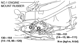
11. Tighten the No.1 engine mount rubber installation bolts.
2WD
ac5wzw00005649
|
4WD
am6zzw00014043
|
12. Install the seal plate. (See OIL PAN REMOVAL/INSTALLATION [SKYACTIV-D 2.2].)
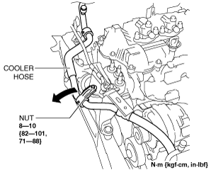
13. Install the wiring harness bracket and cooler hose.
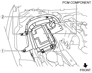
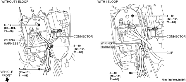
14. Install the PCM component using the following procedure:
am6zzw00011367
|
am6zzw00010090
|
am6zzw00010091
|
am6zzw00011368
|
15. Install the clips shown in the figure. (With i-ELOOP)
am6zzw00010084
|
16. Install the bolt shown in the figure. (With i-ELOOP)
am6zzw00011363
|
17. Connect the generator terminal B cable. (With i-ELOOP) (See GENERATOR REMOVAL/INSTALLATION [SKYACTIV-D 2.2 (WITH i-ELOOP)].)
18. Connect the service plug. (With i-ELOOP) (See SERVICE PLUG DISCONNECTION/CONNECTION [i-ELOOP].)